Optional Connections (continued)
E n g l i s h
| SPLITTER |
Antenna/cable TV | 1 |
signals |
|
VHF/UHF | OUT |
RF IN |
|
| VIDEO |
| OUT |
| AUDIO |
| L |
VHF/UHF | AUDIO |
RF OUT | R |
Back of aVCR (Example only)
IN
VIDEO
IN
AUDIO
L
AUDIO
R
4
IN |
|
| OUT | Back of a Cable Box | |
VIDEO | R | or Satellite Receiver | |||
RF | L | ||||
|
| AUDIO |
| ||
|
|
|
| (Example only) |
3
5
2
TV
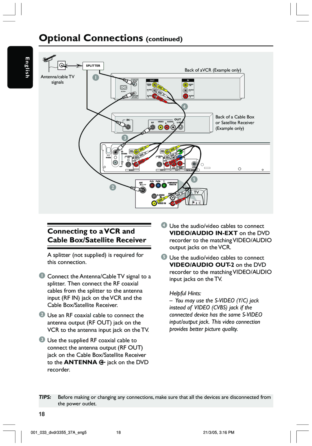
Connecting to a VCR and Cable Box/Satellite Receiver
A splitter (not supplied) is required for this connection.
1Connect the Antenna/Cable TV signal to a splitter. Then connect the RF coaxial cables from the splitter to the antenna input (RF IN) jack on the VCR and the Cable Box/Satellite Receiver.
2Use an RF coaxial cable to connect the antenna output (RF OUT) jack on the VCR to the antenna input jack on the TV.
3Use the supplied RF coaxial cable to connect the antenna output (RF OUT) jack on the Cable Box/Satellite Receiver to the ANTENNA ![]() jack on the DVD recorder.
jack on the DVD recorder.
4Use the audio/video cables to connect VIDEO/AUDIO
5Use the audio/video cables to connect VIDEO/AUDIO
Helpful Hints:
– You may use the
TIPS: Before making or changing any connections, make sure that all the devices are disconnected from the power outlet.
18
001_033_dvdr3355_37A_eng5 | 18 | 21/3/05, 3:16 PM |