10 Hookups (cont’d)
Connecting to a TV Only
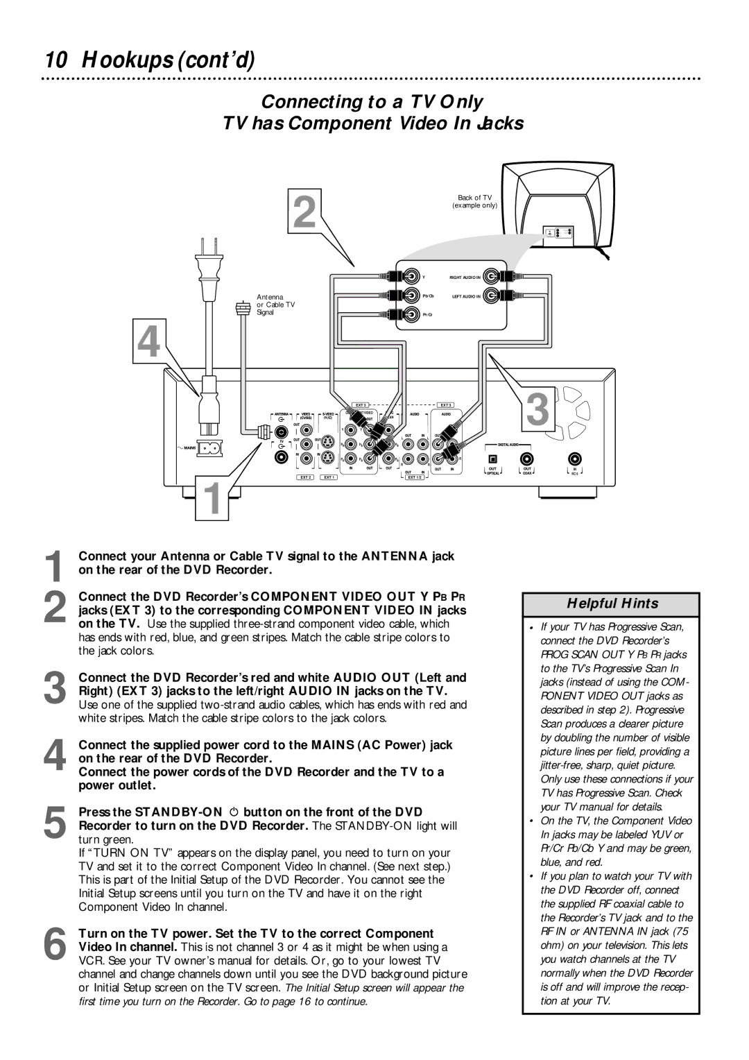
TV has Component Video In Jacks
2
Antenna
or Cable TV Signal
4
Back of TV
(example only)
Y | RIGHT AUDIO IN |
Pb/Cb | LEFT AUDIO IN |
Pr/Cr |
|
|
| EXT 3 |
| EXT 3 | 3 |
|
| VIDEO | PROG |
| |
|
|
| SCAN |
| |
| Y | Y | Y |
| |
|
|
| L | L |
|
| PB | PB | PB |
|
|
| PR | PR | PR |
| R |
|
|
| R | R |
|
|
|
|
|
| IN |
EXT 2 | EXT 1 |
|
| EXT 1/2 | RC 6 |
|
|
|
1
1 Connect your Antenna or Cable TV signal to the ANTENNA jack on the rear of the DVD Recorder.
2 Connect the DVD Recorder’s COMPONENT VIDEO OUT Y PB PR jacks (EXT 3) to the corresponding COMPONENT VIDEO IN jacks on the TV. Use the supplied
3 Connect the DVD Recorder’s red and white AUDIO OUT (Left and Right) (EXT 3) jacks to the left/right AUDIO IN jacks on the TV. Use one of the supplied
4 Connect the supplied power cord to the MAINS (AC Power) jack on the rear of the DVD Recorder.
Connect the power cords of the DVD Recorder and the TV to a power outlet.
5 Press the
If “TURN ON TV” appears on the display panel, you need to turn on your TV and set it to the correct Component Video In channel. (See next step.) This is part of the Initial Setup of the DVD Recorder. You cannot see the Initial Setup screens until you turn on the TV and have it on the right Component Video In channel.
6 Turn on the TV power. Set the TV to the correct Component Video In channel. This is not channel 3 or 4 as it might be when using a VCR. See your TV owner’s manual for details. Or, go to your lowest TV channel and change channels down until you see the DVD background picture or Initial Setup screen on the TV screen. The Initial Setup screen will appear the first time you turn on the Recorder. Go to page 16 to continue.
Helpful Hints
•If your TV has Progressive Scan, connect the DVD Recorder’s PROG SCAN OUT Y PB PR jacks to the TV’s Progressive Scan In jacks (instead of using the COM- PONENT VIDEO OUT jacks as described in step 2). Progressive Scan produces a clearer picture by doubling the number of visible picture lines per field, providing a
•On the TV, the Component Video In jacks may be labeled YUV or Pr/Cr Pb/Cb Y and may be green, blue, and red.
•If you plan to watch your TV with the DVD Recorder off, connect the supplied RF coaxial cable to the Recorder’s TV jack and to the RF IN or ANTENNA IN jack (75 ohm) on your television. This lets you watch channels at the TV normally when the DVD Recorder is off and will improve the recep- tion at your TV.