Page
Page
Table of contents
Recording on the HDD
Disc Manager DM
Playback from the HDD
Recording on a DVD+RW, DVD+R
DVD recorder display
Access control Child Lock
Information on the screen of your TV95
TV brands supported code numbers
Introduction
Convenience of watching
Convenience of editing
Convenience of programming
Convenience of recording
Convenience of archiving
Do not Move the SET When Switched on
Important instructions for the HDD
Alaser
Trademark and license information
Important information for customers in Great Britain
Content of the box
Remote control and batteries Mains cable Transmitter
Remote control
Remote control buttons
Introduction to the set
Info
System Menu
Disc Menu
Browser HDD
Front of the device
Back of the device
Type plate
Installation
Preparing the remote control for operation
Using your DVD remote control With your TV
Connecting the scart cable
Connecting to the TV standard configuration
Connecting the aerial
Connection with the aerial cable only
Connection via a S Y/C cable
Connecting to the TV alternative configurations
Connection via composite video Cvbs cable
Preparation
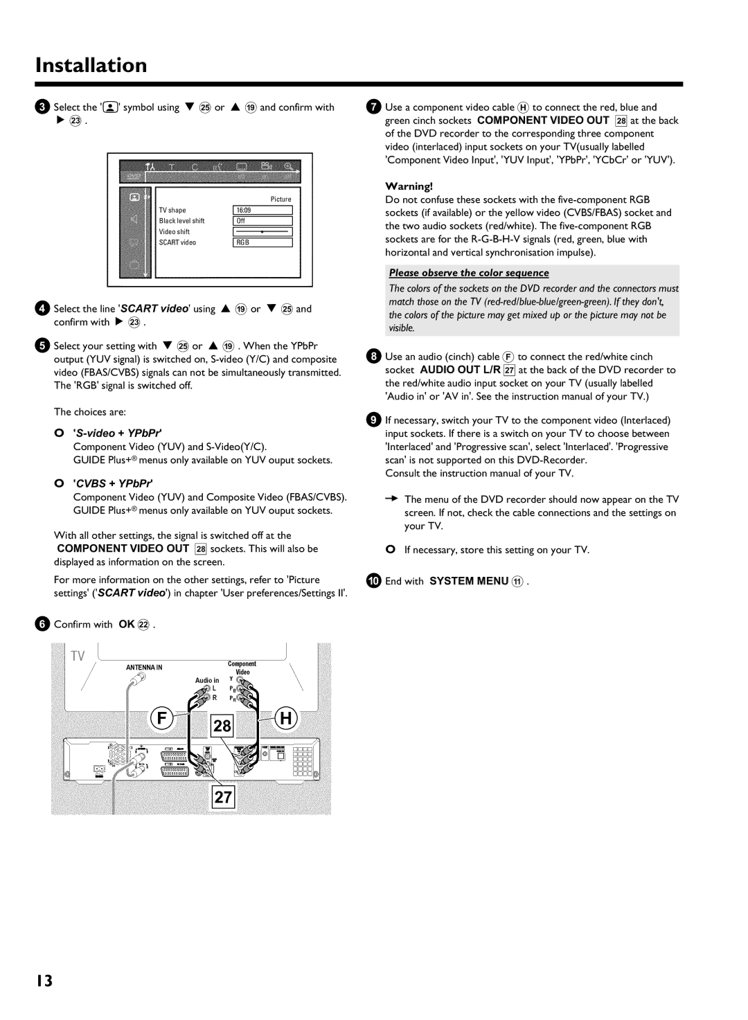
Please observe the color sequence
Video + YPbPr
Cvbs + YPbPr
0End with System Menu a
Connecting additional devices
Connecting additional devices to the second scart socket
Connecting an external receiver
Connecting G transmitter
Connecting additional devices via aerial cable only
How do I find the right position?
Connecting a camcorder to the front sockets
Digital DV input socket Input socket
Video Cvbs input socket
Connecting audio devices to the digital audio sockets
Connecting audio devices
Connecting to the analog audio sockets
Can I use the Phono input on my amplifier?
Switching on additional devices
Initial Installation
Connecting to the mains
No aerial connected
Letterbox
Panscan
1609
Please have patience
Initial installation is now complete
No TV-Stations found yet?
Sound may be distorted on some TV channels
Language
Initial Installation of the Guide Plus+ system
Setting up the Guide Plus+ System
Country
Finalise set
External receiver
Cannot enter a local post code
If you do not find your brand, proceed as follows
My receiver does not display the programme number
My brand is not included in the list
Channel r S
Confirm with OK L on the remote control
Want to install additional external receivers
My external receiver does not display the programme number
Finalise set up of the external receiver
Dont switch off the Guide Plus+ data channel Right tile
Left tile
Additional installation features
Allocating a decoder
Using Standby m
Cannot switch my TV to programme number
Switch off recorder, new preset appears on the screen
Sorting TV channels with Follow TV
Manual TV channel search
TV channel name, press C M
Nicam
Switch off the DVD recorder using Standby m
Sorting and deleting TV channels manually
Deleting TV channels
Automatic TV channel search Autoinstall
Setting the time and date
Time/date is displayed incorrectly despite manual setting
Setting the language
Audio Language
Menu
Using the Guide Plus+ System
Guide Plus+ System
General information
Grid screen
Home blue buttonG
Search screen
Record red buttonD
Colours of the categories
Programming from the Grid screen
Schedule screen
Info screen
Programming from the Schedule screen
Editor screen
Setup screen
Setup
View Demo
Discs you can use
Cleaning the discs
Playback from an optical disc
Regional code
Inserting a disc
Switch over to the actual TV channel during playback
Opening/closing the tray using the remote control
Playing a DVD video disc
Playing a DVD+RW/ +R disc
Playing an audio CD
MP3 CD display
Playing an MP3 CD
Playing a Super Video CD
Cannot playback SuperVideo CDs
Searching on disc DVD, SVCD, CD
Additional playback features
General
Still picture DVD, SVCD, CD
Repeat/Shuffle play DVD, Svcd
Scan feature DVD
Search by time DVD, Svcd
Repeating a passage a
Camera angle DVD
Zoom feature DVD, Svcd
F symbol will be hidden
Select the audio language DVD, Svcd
Subtitles DVD
Disc Manager DM
General information
Adding a disc to the Disc Manager
Why do I need to label the discs?
Disc contents are not deleted
Removing discs from the Disc Manager
What do the displays on the screen mean?
Searching for a title in the Disc Manager
Searching discs
See the message Insert disc number on my screen
Playback from the HDD
Auto delete
Change order in the media browser
Colour key functionality in the Media Browser
Navigation in the Time Shift Buffer
What is the advantage from 1 hour and 6 hours?
Time Shift Buffer
HDD buffer
Search by time
Additional playback features
Zoom feature
Repeat
Useful information
Recoding mode
Recording on the HDD
Preferences/Chapters
Starting a recording with data from the Guide Plus+ system
Start manual recordings
Flush/erase the Time Shift Buffer
Press REC/OTR n
End recordings
Recordings from the Time Shift Buffer
Recording from a camcorder connected to the front sockets
How can I delete the changes?
Red light around the record button n 0 is flashing
Copy protection
Recording from a video recorder/DVD player
Stop h N
Please observe
Direct record does not work or recording starts from EXT1
Switching Direct Record on or off
Direct Record
6End with System Menu a
Automatic recording from a satellite receiver sat recording
Recording on a DVD+RW, DVD+R
Discs you can use
Two way compatibility
Jump Back T , Jump FWD W
What is the order of archiving?
Archiving storing titles on a DVD+RW, DVD+R
Interrupt the process
Finalising a DVD+R
Protect disc against accidental recordings
What happens with DVD+R discs?
Programming a recording Timer
Using the Time Shift Buffer
What do I need to know about VPS/PDC?
Programming recordings with the Guide Plus+ System
Guide Plus+ system
Video Plus+ system appears on the screen
Setting up repeat recordings
Programming recordings with the Video PLus+ System
Activate VPS/PDC
Manual programmed recordings
Delete programmed recording
How to change or delete a programmed recording Timer
Cancel a programmed recording in progress
Changing the TV channel
Delete titles/recordings from the HDD
Unprotect the title using the blue function button G
Edit title on HDD
On the screen
Clear chapters
Editing the title stored on the HDD
Title name
Video edit
Enter characters using
Editing the recorded name
Divide title
Insert chapter markers
Insert/remove chapter markers
Hide chapters sections
Remove chapter marker
Archiving of the edited title symbol a
How can I change delete the markers?
OK L
Edit title DVD+RW, DVD+R
My Index-screen looks different
Can markers be set on a DVD+R disc?
Insert chapter markers
Hiding chapters
Will appear on the screen
Number of chapters C has increased by two or more numbers
Switching quickly
Deleting chapter markers
This function is independent from the selected line
Changing the index picture
Dividing titles
Can I divide titles on DVD+R discs?
Editing recording titles name
Playing the entire title
How can I enter the characters with the buttons 0..9 ?
Erasing recordings/titles
Can titles be deleted from a DVD+R disc?
Disc information and status
Changing the disc name
Press Disc Menu B
Finishing editing
Finalising DVD+R discs
Erasing DVD+RW Discs
Menu overview
Picture
Set up
User preferences / settings
Zoom
Record mode
Audio
Time search
HDD buffer
Camera mode
Chapters
Sat record
Jump forward
Safety Slot
Installation
Jump back
TV shape
User preferences /settings
Picture settings
Black level shift
Scart video
Sound settings
Night mode
Digital output
Language settings
Additional settings
Auto resume
Disk feature menu
Access Control
Finalise disc
Activating/deactivating child lock
Access control Child Lock
Child lock HDD, DVD, Svcd
Authorising a disc
Changing the country
Parental level control DVD
Activating/deactivating parental level control
What do the ratings mean?
Changing the PIN code
Have forgotten my code
Field for temporary messages
Symbols in the menu bar
Information on the screen of your TV
Menu bar
Disc type symbols
Symbols in the Media Browser
Symbols in the Time Shift Buffer
Operating mode symbols
Symbols on your DVD recorder display
DVD recorder display
Messages in the DVD recorder display
An empty title on a DVD+RW, DVD+R is selected
BThere is no power supply check the power supply
Before you call an engineer
BImportant
100
No playback on DVD recorder
101
Press GUIDE/TV J
PROBLEM/HINTS Solution
102
Press Browser HDD H and then System Menu a
103
Hidden scenes on a DVD+RW are still visible on my
End with System Menu a
Have forgotten
BTo erase the PIN code reset to 0000, proceed as follows
104
First press Disc Menu B then System Menu a
Ntsc
Glossary
105
PAL
106
TV brands supported code numbers
107
108
MGA
WwnnNNNwwnnwWNnwNwnNwnnNWnWwnN Dvdr 725H/05
109
Technical data
Audio Format DVD/CD playback
Dvdr 725H/05
Philips Norge AS Philips PORTUGUESA, S.A