5.4Mounting in a 19” rack
The SM30 Control Centre is available in two versions:
LBB 1280/30 for table top use including the cover.
LBB 1280/40 for 19” rack mounting, without cover but including the mounting brackets.
Removing Feet
WARNING: Before attempting to open the housing, the mains lead and the 48 V DC battery plug should be disconnected. It is not sufficient to merely switch off the ON/OFF switch on the front panel.
The feet of the Control Centre may be removed for rack mounting if space is limited. To remove the feet simply unscrew the
If rack space is not limited however, it is preferable to leave the feet in position and to mount a narrow blank rack panel beneath the unit. If the Control Centre then has to be removed for servicing, the feet will protect the surface of furniture from being
scratched by metal components of SM30.
Calculating Required Rack Space
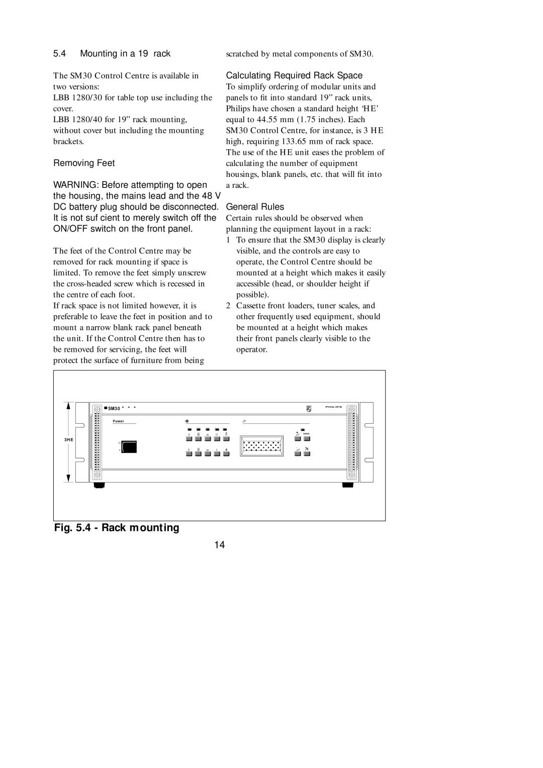
To simplify ordering of modular units and panels to fit into standard 19” rack units, Philips have chosen a standard height ‘HE’ equal to 44.55 mm (1.75 inches). Each SM30 Control Centre, for instance, is 3 HE high, requiring 133.65 mm of rack space. The use of the HE unit eases the problem of calculating the number of equipment housings, blank panels, etc. that will fit into a rack.
General Rules
Certain rules should be observed when planning the equipment layout in a rack:
1To ensure that the SM30 display is clearly visible, and the controls are easy to operate, the Control Centre should be mounted at a height which makes it easily accessible (head, or shoulder height if possible).
2Cassette front loaders, tuner scales, and other frequently used equipment, should be mounted at a height which makes their front panels clearly visible to the operator.
SM3 0 | PHILIPS |
| |
Po we r |
|
| + |
3H E |
|
| - |
Fig. 5.4 - Rack mounting
14