12.2Coupling Zone Relay Modules
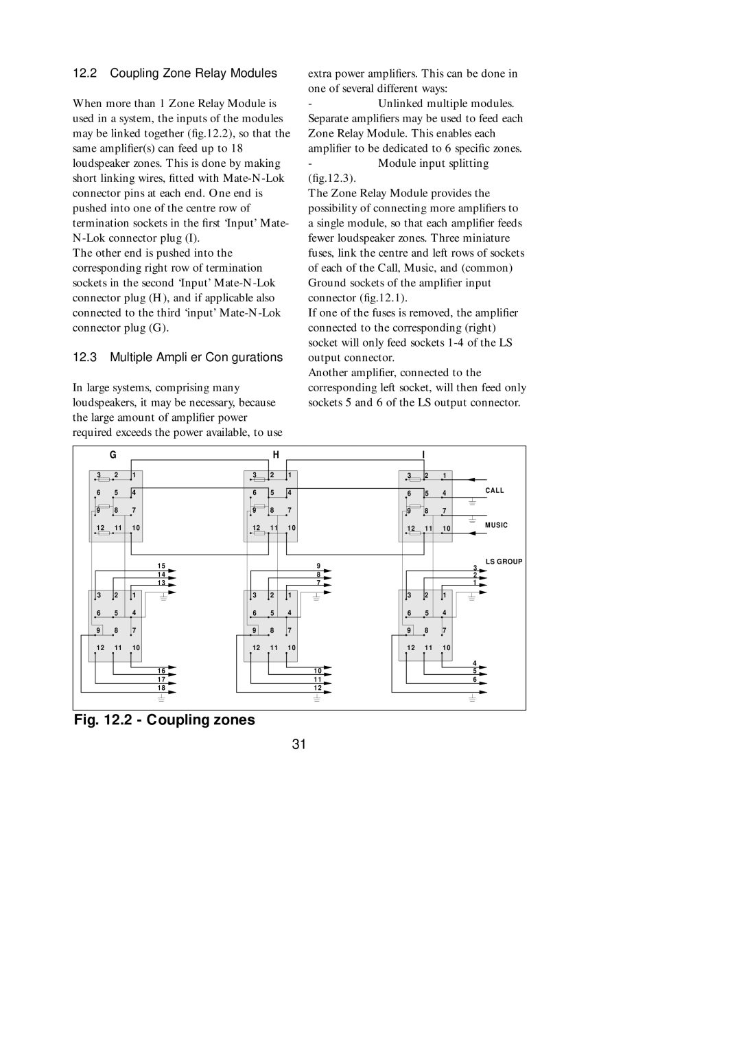
When more than 1 Zone Relay Module is used in a system, the inputs of the modules may be linked together (fig.12.2), so that the same amplifier(s) can feed up to 18 loudspeaker zones. This is done by making short linking wires, fitted with
The other end is pushed into the corresponding right row of termination sockets in the second ‘Input’
12.3Multiple Amplifier Configurations
In large systems, comprising many loudspeakers, it may be necessary, because the large amount of amplifier power required exceeds the power available, to use
extra power amplifiers. This can be done in one of several different ways:
-Unlinked multiple modules. Separate amplifiers may be used to feed each Zone Relay Module. This enables each amplifier to be dedicated to 6 specific zones.
-Module input splitting
(fig.12.3).
The Zone Relay Module provides the possibility of connecting more amplifiers to a single module, so that each amplifier feeds fewer loudspeaker zones. Three miniature fuses, link the centre and left rows of sockets of each of the Call, Music, and (common) Ground sockets of the amplifier input connector (fig.12.1).
If one of the fuses is removed, the amplifier connected to the corresponding (right) socket will only feed sockets
Another amplifier, connected to the corresponding left socket, will then feed only sockets 5 and 6 of the LS output connector.
| G |
|
| H |
|
| I |
|
|
3 | 2 | 1 | 3 | 2 | 1 | 3 | 2 | 1 |
|
6 | 5 | 4 | 6 | 5 | 4 | 6 | 5 | 4 | CALL |
| |||||||||
9 | 8 | 7 | 9 | 8 | 7 | 9 | 8 | 7 |
|
12 | 11 | 1 0 | 12 | 11 | 10 | 12 | 11 | 10 | MUSIC |
| |||||||||
|
| 15 |
|
| 9 |
|
|
| LS GROUP |
|
|
|
|
|
|
| 3 | ||
|
| 14 |
|
| 8 |
|
|
| 2 |
|
| 13 |
|
| 7 |
|
|
| 1 |
3 | 2 | 1 | 3 | 2 | 1 | 3 | 2 | 1 |
|
6 | 5 | 4 | 6 | 5 | 4 | 6 | 5 | 4 |
|
9 | 8 | 7 | 9 | 8 | 7 | 9 | 8 | 7 |
|
12 | 11 | 10 | 12 | 11 | 10 | 12 | 11 | 10 |
|
|
| 1 6 |
|
| 10 |
|
|
| 4 |
|
|
|
|
|
|
| 5 | ||
|
| 1 7 |
|
| 11 |
|
|
| 6 |
|
| 1 8 |
|
| 12 |
|
|
|
|
Fig. 12.2 - Coupling zones
31