VSX-84TXSi VSX-84TXSi-S VSX-82TXS VSX-82TXS-S
AUDIO/VIDEO MULTI-CHANNEL RECEIVER
Operating Instructions
Register your product at
FEDERAL COMMUNICATIONS DECLARATION OF CONFORMITY
KEEP IN A SECURE AREA. THIS IS FOR YOUR SECURITY
Information to User
IMPORTANT SAFETY INSTRUCTIONS
RISK OF ELECTRIC SHOCK DO NOT OPEN
Contents
06 Using the tuner
03 Connecting your equipment
07 The System Setup menu
09 Other Settings
10 Using other functions
11 Controlling the rest of your system
12 Additional information
Installing the receiver
Main remote control unit Sub room remote control unit VSX-84TXSi Only
Before you start
01 Before you start Chapter
Automatically setting up for surround sound MCACC
4 Use the on-screen automatic MCACC setup to set up your system
5 minute guide
5 minute guide Chapter
1 Switch on the receiver and your TV
4 Select ‘Auto MCACC’ from the System Setup menu then press ENTER
02 5 minute guide
6 Follow the instructions on-screen
Better sound using Phase Control
Problems when using the Auto MCACC Setup
Press PHASE PHASE CONTROL to switch on phase correction
5 minute guide
Connecting your equipment
03 Connecting your equipment Chapter
Connecting digital audio sources on page
Using the i.LINK interface on page
Connecting your equipment
When making cable connections
Connecting your TV and DVD player on page
Connecting a DVD/HDD recorder, VCR and other video sources on page
03 Connecting your equipment Connecting your TV and DVD player
the multichannel analog inputs on page
Connecting a satellite/cable receiver
or other set-top box
and other video sources
2 Connect an optical-type2 digital audio output from
03 Connecting your equipment
Using the component video jacks
3 If the device can output digital audio, connect an
Connecting your equipment Connecting digital audio sources
About the WMA9 Pro decoder
03 Connecting your equipment Connecting analog audio sources
Connecting a component to the front panel inputs
Installing your speaker system
Connecting the speakers
Connecting your equipment
Center
Bare wire connections
Placing the speakers
Banana plug connections
fig. A
Connecting antennas
THX speaker system setup
2 Pull off the protective shields of both AM antenna wires
4 Release the tabs to secure the AM antenna wires
FM wire antenna
Connecting external antennas
Plug the AC power cord into a convenient AC power outlet
Plugging in the receiver
4 PHASE CONTROL indicator
6 HDMI indicator
7 Digital Precision Processing indicator
Controls and displays
Operating range of remote control unit
9 MCACC indicator
10 i.LINK indicator VSX-84TXSi only
12 MASTER VOLUME dial 13 Front panel controls
1 SIGNAL indicators
2 Program format indicators
3 Digital format indicators
8 Sound processing indicators
04 Controls and displays Remote control
5 Tuner/component control buttons/SETUP
1 RECEIVER
2 INPUT SELECT
PRESET - See Selecting preset codes directly on page
LEARNING - See Programming signals from other remote controls on page
ERASE - See Erasing one of the remote control button settings on page
RESET - See Resetting the remote control presets on page
04 Controls and displays Sub remote control unit
13 VOLUME +
VSX-84TXSi only
2 Input source buttons
Listening to your system
Listening to your system
Listening in surround sound
Auto playback
Using the Home THX modes
Using the Advanced surround effects
05 Listening to your system
2 Pro Logic IIx MUSIC - See above
Using Stream Direct
Selecting MCACC presets
Listening in stereo
While listening to a source, press STEREO for stereo playback
05 Listening to your system Choosing the input signal
Using surround back channel processing
Using the Virtual Surround Back mode
Using the Sound Retriever
VirtualSB OFF - Virtual Surround Back mode is switched off
Listening to your system
Using the tuner
06 Using the tuner Chapter
Tuning directly to a station
Automatic tuning
Using the tuner Saving station presets
Naming station presets
Listening to station presets
1 Choose the station preset you want to name
The System Setup menu
07 The System Setup menu Chapter
Making receiver settings from the System Setup menu
2 Press RECEIVER on the remote control, then press the SETUP button.2
The System Setup menu
2 Select ‘Auto MCACC’ from the System Setup menu then press ENTER
5 Wait for the Auto MCACC Setup to finish outputting test tones
4 Follow the instructions on-screen
07 The System Setup menu
Surround back speaker setting
6 If necessary, confirm the speaker configuration in the OSD.1
7 Make sure ‘OK’ is selected, then press ENTER
Manual MCACC setup
1 Select ‘Surr Back System’ from the System Setup menu
2 Select the surround back speaker setting
3 When you’re finished, press RETURN
2 Adjust the level of the left channel
1 Select ‘Fine SP Distance’ from the Manual MCACC setup menu
4 When youre finished, press RETURN
2 Adjust the distance of the left channel from the listening position
1 Select ‘Standing Wave’ from the Manual MCACC setup menu
3 When youre finished, press RETURN
1 Select ‘EQ Adjust’ from the Manual MCACC setup menu
3 Select the channels you want and adjust to your liking
How to use Professional Acoustic Calibration EQ
How to interpret the graphical output
07 The System Setup menu
Using Professional Acoustic Calibration EQ
and time setting. Use the
buttons to switch
1 Select ‘EQ Professional’ then press ENTER
07 The System Setup menu Data Management
Copying MCACC preset data
Checking MCACC preset data
1 Select ‘Data Management’ from the System Setup menu
Manual speaker setup
Speaker Setting
Renaming MCACC presets
Clearing MCACC presets
1 Select ‘Channel Level’ from the Manual SP Setup menu
2 Select a setup option
3 Confirm your selected setup option
4 Adjust the level of each channel using the buttons
1 Select ‘Speaker Distance’ from the Manual SP Setup menu
2 Adjust the distance of each speaker using the buttons
1 Select ‘Bass Peak Level’ from the Manual SP Setup menu
Speaker Distance
THX Audio Setting
1 Select ‘X-Curve’ from the Manual SP Setup menu
2 Choose the X-Curve setting you want
1 Select ‘THX Audio Setting’ from the Manual SP Setup menu
Connecting an iPod
Connecting your iPod to the receiver
1 Switch the receiver into standby then use the
Other connections
Using XM Radio
Watching photos and video content
Connecting your XM Radio receiver
08 Other connections
Using XM HD Surround
Saving channel presets
Other connections
Listening to XM Radio
Connecting using HDMI
Using the XM Menu
Listening to channel presets
1 Press CLASS to select the class in which the channel is stored
Using the i.LINK interface
About HDMI
Other connections
You can’t hear HDMI audio through this receiver’s digital out jacks
About i.LINK
Checking the i.LINK inputs
08 Other connections
About PQLS rate control
Creating an i.LINK network
1 IEEE Std. 1394a-2000, Standard for a High Performance Serial Bus
Other connections
08 Other connections Connecting the multichannel analog inputs
Using the USB interface
Selecting the multichannel analog inputs
VSX-84TXSi only
Second Zone speaker B setup
Switching the speaker system
2 Switch on your computer and this receiver
6 Turn up the volume control on your computer and this receiver
Bi-wiring your speakers
2 Select the ‘Front Bi-Amp’ setting from the ‘Surr Back System’ menu
Bi-amping your front speakers
1 Connect your speakers as shown below
Multi-room listening
Making multi-room connections
DIGITAL IN
ANALOG
Basic multi-room setup ROOM
Surround Back System multi-room setup ROOM
Secondary multi-room setup ROOM
Multi-room listening options
Connecting an IR receiver
Using the multi-room controls
Multi-room remote controls
4 Use the MASTER VOLUME dial to adjust the volume
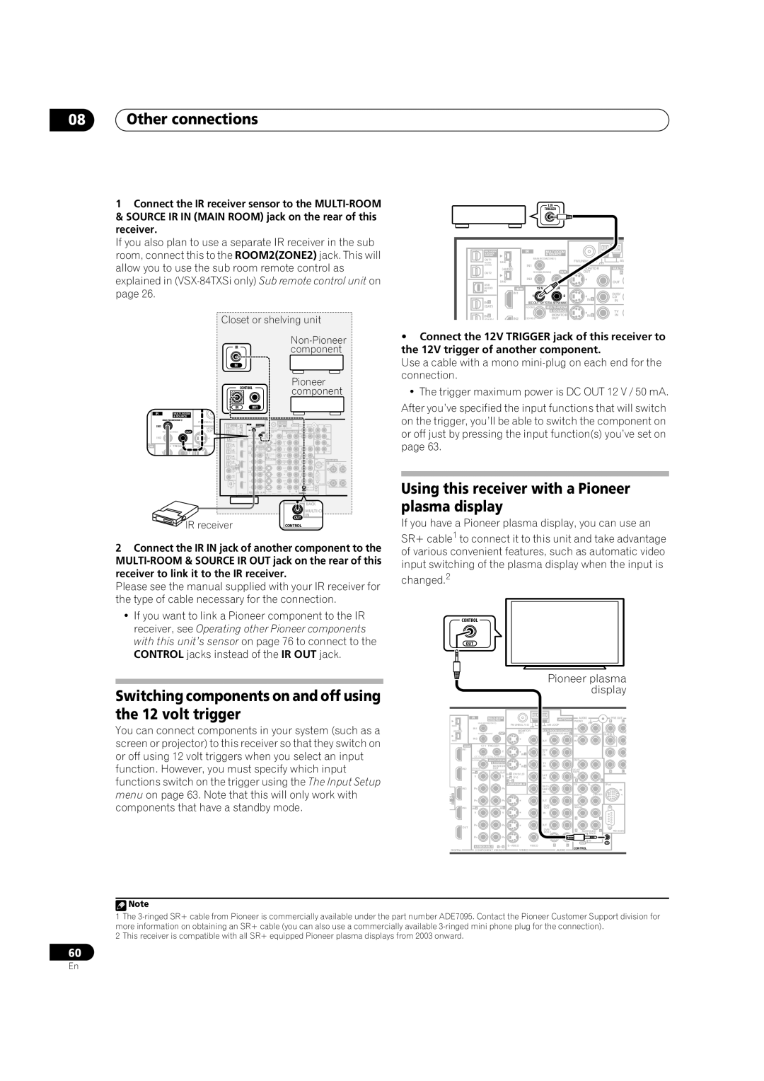
Switching components on and off using the 12 volt trigger
Using this receiver with a Pioneer plasma display
08 Other connections
Pioneer plasma
Using the SR+ mode with a Pioneer plasma display
2 To switch SR+ mode on/off, press RECEIVER, then the SR+ button
DVD player
Pioneer plasma
Connecting a PC for Advanced MCACC output
Advanced MCACC output using your PC
3 When you’re finished, press RETURN
08 Other connections
Other Settings
Other Settings
The Input Setup menu
4 Select the input function that you want to set up
09 Other Settings
The Other Setup menu
Input function default and possible settings
3 Select ‘Other Setup’ then press ENTER
Multi-Room Setup
SR+ Setup for Pioneer plasma displays
OSD Adjustment
1 Select ‘Multi-Room Setup’ from the System Setup menu
Using other functions
10 Using other functions Chapter
Setting the AV options
Setting
Using other functions
Playing a different source when recording
Making an audio or a video recording
1 Select the source you want to record
10 Using other functions
Reducing the level of an analog signal
Using the sleep timer
Switching the speaker impedance
Checking your system settings
Resetting the system
Default system settings
Default
10 Using other functions
Setting
Default
MCACC
Setting the remote to control other components
Selecting preset codes directly
remote controls
Programming signals from other
Erasing one of the remote control button settings
Resetting the remote control presets
Confirming preset codes
2 Use to select RESET then press ENTER
4 Use to switch direct function ON or OFF then press ENTER
Renaming input source names
Direct function
Multi Operation and System Off
Using multi operations
Using System off
7 Select the button for the command you want to input
8 Repeat steps 5-7 to program a sequence of up to five commands
Controlling the rest of your system Controls for TVs
Controls for other components
Buttons
Function
Operating other Pioneer components with this unit’s sensor
Button s
1 Decide which component you want to use the remote sensor of
11 Controlling the rest of your system
Troubleshooting
Power
Symptom
Additional information
Other audio problems
12 Additional information
Symptom
Symptom
Video
Symptom
Symptom
Additional information
Settings
Display
Professional Calibration EQ graphical output
Symptom
Remote control
i.LINK interface
Symptom
Symptom
i.LINK messages
USB interface
HDMI
Message
iPod messages
XM radio messages
Cause
Action
12 Additional information Surround sound formats
Dolby
Windows Media Audio 9 Professional
Dolby Digital
About THX
THX Cinema processing
Re-Equalization
Timbre Matching
Listening modes with different input signal formats
Stereo 2 channel signal formats
THX MusicMode
THX Games Mode
Multichannel signal formats
Input signal format
Auto Surround
Additional information
Stream direct with different input signal formats
Surround Back speakers
Stereo 2 channel signal formats
Multichannel signal formats
Additional information Specifications
Cleaning the unit
Amplifier section
Audio Section
Features
Easy setup using Advanced MCACC
Phase correction
12 Additional information Our philosophy
We Want You Listening For A Lifetime
Additional information
To establish a safe level
Once you have established a comfortable sound level
PIONEER CORPORATION
PIONEER ELECTRONICS USA INC
PIONEER ELECTRONICS OF CANADA, INC
PIONEER EUROPE NV

 Note
Note