08Other connections

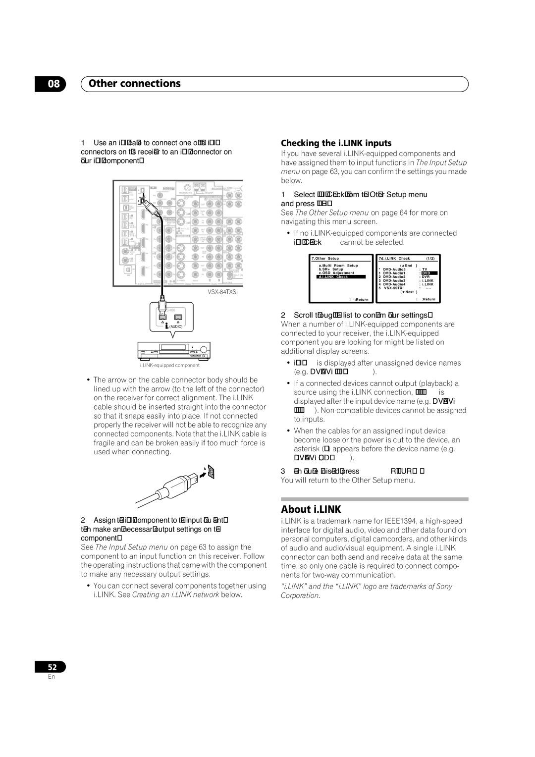
1 Use an i.LINK cable to connect one of the i.LINK

Checking the i.LINK inputs


connectors on this receiver to an i.LINK connector on

If you have several i.LINK-equipped components and

your i.LINK component.


have assigned them to input functions in The Input Setup


menu on page 63, you can confirm the settings you made


below.


MULTI-ROOM


IR

MULTI-ROOM


ANTENNA

AUDIO


& SOURCE


& SOURCE


PHONO


/ REC SEL


MAIN ROOM(ZONE1)


1 Select ‘i.LINK Check’ from the Other Setup menu

OUT1

(AUDIO)


MONITOR

MULTI-ROOM & SOURCE

IN


IN1


ROOM3

S400


FM UNBAL 75 Ω

AM LOOP


(ZONE3)


OUT2


ROOM2(ZONE2) OUT


OUT

R ROOM2(ZONE2) L

CD


and press ENTER.


USB


IN2


S400


OUT

IN


AUDIO


12 V TRIGGER


See The Other Setup menu on page 64 for more on

IN

IN1

(DC

12V TOTAL 50 mA MAX)


IN 1

IN


IN 1


2


LD


(SAT)

IN2

ROOM2

MULTI-ROOM


OUT


navigating this menu screen.


(DVR/

(ZONE2)

OUT


TV

CD-R/


& SOURCE


IN 2


MONITOR


IN 2

IN


VCR 1)


IN 1

OUT IN 1 (DVD/LD)

SAT

TAPE

FL

• If no i.LINK-equipped components are connected

VCR 2)


Y

Y

ASSIGNABLE

IN

FR

IN 3


IN 2

(TV)

IN


(DVR/


1

2


R

L


IN 4

IN3

PB

PB


VIDEO /


i.LINK Check cannot be selected.


GAME1


ASSIGNA-


IN


(CD-R)


1

4


SUB W.

CENTER


BLE


PR

PR


OUT


IN 1 1

2


DVR/

SUR-


(DVD/

IN4

IN 2

IN 3


VCR 1

ROUND


LD)


IN 2


Y

Y


IN


7.Other Setup

7d.i.LINK Check

(1/2)


R


(CD)


L


OUT

PB

PB


OUT


a.Multi Room Setup


( End

)

IN


VCR 2

R SURROUND L

b.SR+ Setup

*

DVD-Audio5

: TV


DVR/


BACK

c.OSD Adjustment

1

DVD-Audio1

: DVD

XM


PR

PR


IN


MULTI CH


d.i.LINK Check

2

DVD-Audio2

: DVR


OUT

IN


ASSIGNABLE 1 3

S - VIDEO VIDEO

R L


3

DVD-Audio3

: i.LINK


DIGITAL

COMPONENT VIDEO


VIDEO

AUDIO

CONTROL


4

DVD-Audio4

: i.LINK


VSX-84TXSi


5

VSX-59TXi

: ----


( Next )


:Return


:Return


S400


2 Scroll through the list to confirm your settings.


(AUDIO)


When a number of i.LINK-equipped components are


connected to your receiver, the i.LINK-equipped


component you are looking for might be listed on


additional display screens.


i.LINK-equipped component

The arrow on the cable connector body should be lined up with the arrow (to the left of the connector) on the receiver for correct alignment. The i.LINK cable should be inserted straight into the connector so that it snaps easily into place. If not connected properly the receiver will not be able to recognize any connected components. Note that the i.LINK cable is fragile and can be broken easily if too much force is used when connecting.

i.LINK is displayed after unassigned device names (e.g. DV-79AVi [i.LINK]).

If a connected devices cannot output (playback) a source using the i.LINK connection, [- - - -]is displayed after the input device name (e.g. DV-79AVi [- - - -]). Non-compatible devices cannot be assigned to inputs.

When the cables for an assigned input device become loose or the power is cut to the device, an asterisk (*) appears before the device name (e.g. *DV-79AVi [CD]).

3When you're finished, press RETURN. You will return to the Other Setup menu.

About i.LINK

2Assign the i.LINK component to the input you want, then make any necessary output settings on the component.

See The Input Setup menu on page 63 to assign the component to an input function on this receiver. Follow the operating instructions that came with the component to make any necessary output settings.

You can connect several components together using i.LINK. See Creating an i.LINK network below.

i.LINK is a trademark name for IEEE1394, a high-speed interface for digital audio, video and other data found on personal computers, digital camcorders, and other kinds of audio and audio/visual equipment. A single i.LINK connector can both send and receive data at the same time, so only one cable is required to connect compo- nents for two-way communication.

“i.LINK” and the “i.LINK” logo are trademarks of Sony Corporation.

52

En

Page 52
Image 52
Pioneer VSX-84TXSI, VSX-82TXS-S, VSX-84TXSi-S manual About i.LINK, Checking the i.LINK inputs

VSX-84TXSi-S, VSX-82TXS, VSX-82TXS-S, VSX-84TXSI specifications

The Pioneer VSX-84TXSi, VSX-82TXS, VSX-84TXSi-S, and VSX-82TXS are part of Pioneer's renowned lineup of home theater receivers, notable for their impressive audio capabilities and advanced features. Designed for enthusiasts who appreciate high-quality sound, these receivers stand out in the crowded market of A/V receivers.

The VSX-84TXSi and VSX-84TXSi-S come equipped with a robust 7.1-channel amplifier configuration, delivering a powerful output that ensures dynamic and immersive audio experience. Both models boast Pioneer's sophisticated Class D3 amplification technology, which efficiently provides high power output while minimizing distortion and heat. This feature allows listeners to enjoy their favorite music and movies with clarity and depth.

One standout feature of these receivers is the Advanced MCACC (Multi-Channel Acoustic Calibration System) technology. This automatically adjusts the speaker settings to fit the unique acoustics of the room, ensuring balanced sound across all channels. The calibration process is user-friendly, allowing even novice users to achieve optimal sound performance.

In terms of connectivity, the VSX-84TXSi and VSX-82TXS are equipped with multiple HDMI inputs, supporting the latest audio and video formats, including 4K Ultra HD. They also support Dolby TrueHD and DTS-HD Master Audio, which deliver lossless audio quality for a truly cinematic experience at home.

The VSX-84TXSi and VSX-82TXS models feature a user-friendly interface that includes on-screen displays and intuitive controls. They also offer extensive compatibility with various formats, including MP3, WMA, and AAC. For those who want to stream their music, both models have built-in support for networking capabilities, allowing users to connect to their home network and stream content from devices seamlessly.

The VSX-82TXS, while slightly less powerful than the VSX-84TXSi, offers many features that appeal to casual users and audiophiles alike. It retains the same high-quality audio processing and supports a variety of surround sound formats, making it a versatile choice for different media types.

Overall, the Pioneer VSX-84TXSi, VSX-82TXS, VSX-84TXSi-S, and VSX-82TXS are excellent choices for anyone looking to enhance their home entertainment experience. With a blend of advanced technology, impressive audio performance, and user-friendly features, these receivers continue to be favored options for home theater setups.