Polycom RMX 4000 Hardware Guide
Table
Item | Description |
|
|
Standby button | Toggle between CPU activation and standby. |
|
|
RTM ISDN
The RTM ISDN card connects directly to anMPM+/MPMx. The RTM ISDN card routes data between the MPM+/MPMx cards and components of the system, converts ISDN T1/E1 media to IP packets and provides connectivity to external ISDN networks.
The RTM ISDN card is installed on the rear panel of the RMX interfaces between the RMX unit and the ISDN/PSTN switch. In an RMX with a single MPM+/MPMx card – the RTM ISDN card must be installed in the rear panel slot on the same level as the MPM+/MPMx card. In an RMX with at least two MPM+/MPMx cards – the RTM ISDN card can be installed in any two rear panel card slots.
Up to two RTM ISDN cards can be installed in one RMX 4000. Up to a total of 14 E1 or 18 T1 PRI cables can be installed with two RTM ISDN cards.
Each RTM ISDN card includes the following connections:
•1 LAN port
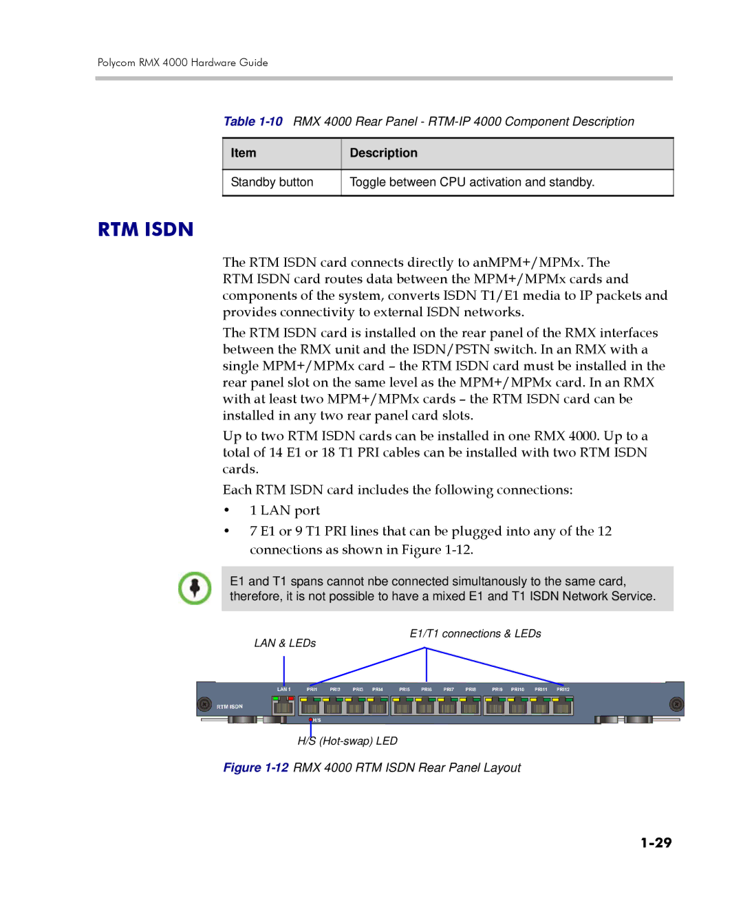
•7 E1 or 9 T1 PRI lines that can be plugged into any of the 12 connections as shown in Figure
E1 and T1 spans cannot nbe connected simultanously to the same card, therefore, it is not possible to have a mixed E1 and T1 ISDN Network Service.
LAN & LEDs
E1/T1 connections & LEDs
H/S