NE0154601-00 B
Document Revision History
Table of Contents
Windows Server 2003, 2008, and 2008 R2 Driver Configuration
Hardware Installation
Windows Server 2003 Driver Installation
Windows Server 2008 and 2008 R2 Driver Installation
Linux Driver Installation and Configuration
Firmware Management
Linux Configuration for Bonding Mode and Virtual LAN Vlan
Troubleshooting Guidelines
Diagnostic Utility Commands Flash Update
Glossary Index List of Figures
11-2 Troubleshooting Tools in Linux
List of Tables
11-3 QLogic Adapter Device IDs
Related Materials
Check the QLogic Web site for updates
Preface
Intended Audience
/lib/modules/kernel-version/kernel/net/netxen
Technical Support
Availability
nx3fwct.bin C\WINDOWS\system32\drivers
Training
Contact Information
Knowledge Database
Preface Technical Support Xii NE0154601-00 B
Product Product Definition Transfer
Overview
QLogic 3000 and 3100 Series Intelligent Ethernet Adapters
Products in -1are supported in this document
Application Notes
iSCSI Boot Setup, part number IS0051404-00
Hardware Requirements
Cable Specifications
Cable Specifications-Optical
System Requirements
Product Cable Type Network Cable Length
Cable Specifications-Copper
Supported QLogic Adapters
SFP+ Optical Module Requirements
Quick Start
QLogic Adapter Installation and Verification
Pre-installation Checklist
QLogic Adapter Installation
Linux
Windows Server Driver Installation
Verify the QLogic Adapter Installation
On Linux systems, execute the following command
Windows Server
Windows Server 2008 and 2008 R2
Nx3fwct.bin Nx3fwmn.bin
Linux Driver Installation
Install the Driver RPM
Red Hat
Suse
Type the following command to install the binary RPM
QLogic Adapter Configuration
QLE3044 Installation
Hardware Installation
Port Number PCI Function Ethernet Interface
Ethernet Port Mapping
QLE3044 Status LEDs
QLE3044 LED Definitions
QLE3044 Bracket Removal
QLE3044 Bracket Removal and Replacement
Module SFP+ Optical
QLE3142 Installation
QLE3142
SFP+ Optical
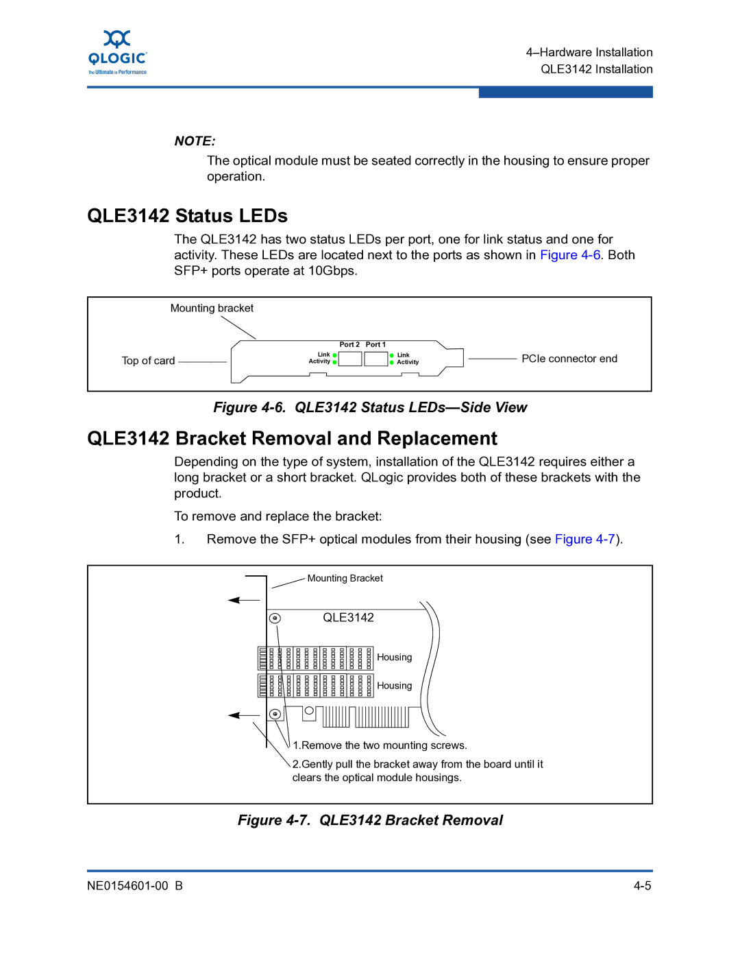
QLE3142 Status LEDs
QLE3142 Bracket Removal and Replacement
QLE3142 Bracket Replacement
Windows Server Driver Installation
Driver Checklist
Firmware ROM Image Location
Windows Server 2003 NIC Driver Installation
Windows Server NIC Driver Installation and Verification
Windows Server 2003-NIC Driver Location Information
Windows Server 2003-Browse for Folder
Click Finish
Windows Server 2003 NIC Driver Installation Verification
Uninstall the NIC Driver
Delete the following files from the corresponding directory
File Directory
Windows Server 2008 2008 R2 Driver Installation
Windows Server 2008 NIC Driver Installation
Setup Wizard dialog box opens see Figure
Click Next
Windows Server 2008-License Agreement
Windows Server 2008 Installation Options
Click Next to begin the installation
Select Installation Folder dialog box opens see Figure
Click Close to complete the installation
Windows Server 2008 NIC Driver Installation Verification
Windows Server 2008-Installation Options
Windows Server 2008 and 2008 R2 Teaming Driver Installation
Click Repair QLogic Advanced Network Config Service
Windows Server 2008 and 2008 R2 Teaming Driver Configuration
NE0154601-00 B
For more help, see the information in the Status box
Right-click Teams, and then click Create Team Figure
13. Windows Server 2008 Teaming-Create Team Window
For more help, see the information in the How-tobox
Windows Server 2008 NIC Driver Uninstall Previous Version
16. Windows Server 2008 Teaming Uninstall Procedure
Windows Server 2008 NIC and Teaming Driver Uninstall
Page
NIC Driver Properties and Configuration
Windows Server 2008, and 2008 R2 Driver Configuration
Adapter Properties-General Tab
Parameter Description
Advanced Properties Parameters
Advanced Properties Parameters
Advanced Properties Parameters
Advanced Properties Parameters
Advanced Properties Parameters
Vlan ID
Network Connections Window
QLogic Adapter Configuration
Local Area Connection Properties Dialog Box
Internet Protocol TCP/IP Properties dialog box opens Figure
QLogic Adapter Diagnostic Tests
Adapter Properties-Diagnostics Tab
Windows Server 2003 Performance
Performance Testing the QLogic Adapter with ntttcp
Run ntttcp
Ntttcp Overview
Ntttcps and ntttcpr Command Line Options
Ntttcps and ntttcpr Command Line Options
Command Default
Data Type Range a Value
Tcp1323Opts
Range
Modifying the Tcp1323Opts Parameter
Hex Value Meaning
Creating the Tcp1323Opts Parameter
CurrentControlSet Services Tcpip Parameters
10. Registry Editor-Parameter Directory
13. Edit Dword Value Window-Tcp1323OptsParameter
Setting the TcpWindowSize Parameter
15. Edit Dword Value Window TcpWindowSize Parameter
14. Modifying the TcpWindowSize Parameter
Page
Linux Driver Installation Configuration
Linux Driver Checklist
Locate the Firmware ROM Image
Verify the Driver Version and Module Information
Enable the Inbox Kernel GPL and Commercial Drivers
Locate the Driver File
Verify the Firmware Version
Check for MSI-X Support
Remove or rename the netxennic.ko file from
Lib/modules/uname -r/kernel/drivers/net/netxen directory
Output of this command is similar to the following
Inbox Kernel GPL Driver and Blacklisting
Some older Linux kernel versions may not support MSI-X
Install the Binary
Preparing for QLogic Adapter Driver Installation
QLogic Adapter Driver Installation RPM Format
Install the Linux Driver Source in RPM Format
nxflash nxudiag phantomcoreP3
Install the QLogic Tools
Type the following command to install the tools
Linux QLogic Adapter Driver Options
Modprobe Command Optional Parameters
Parameter Description Default Range
Parameters are listed in Table
Nxudiag -i ethn command
Configure the QLogic Adapter on Linux
Uninstall the Commercial GPL Driver and Tools Package
Diagnostic Tests for the QLogic Adapter
Linux Performance Tuning
Using the iperf Tool
Performance Tools
Optimization
Here is an example of iperf from the server side
Here is an example of iperf from the client side
Linux Configuration for Bonding Mode and Virtual LAN Vlan
Linux Bonding Mode
Type the following command to bring down the bond
Following message is displayed
Active-Backup or Mode=1
Output for this command is
After 50 seconds, the dmesg command will print
========= down state
Round-Robin or Mode=0
miimon or arpinterval arpiptarget
Dmesg command output is
Bonding Driver Options
Bonding Driver Parameters
Arpinterval
QLogic Adapter Bonding Modes Under Linux
Bonding modes are described in Table
Mode Mode Name Description
Type the following command if the driver has not been loaded
Configuring Virtual LAN Vlan Under Linux
Page
Check for the following entry
Firmware Management
Windows Server Dynamic Firmware Download
Linux Dynamic Firmware Download
Firmware Management Linux Dynamic Firmware Download
Troubleshooting Guidelines
Troubleshooting Tools
Additional Configuration for Windows Server 2008 Teaming
Tool What it Provides
What is Provides
Windows Server Tools
Linux Tools
MSI-X Interrupts for Linux
Check for System Errors
Caveats
Linux
Product Device ID Description
PCI Express Slot
QLogic Adapter Device IDs
You should see a message similar to
C0 10 00 02 00 02 80 00 00 00 10 0b 00 82 04 00
Diagnostic Utility Commands
Table A-1. Diagnostic Utility Commands
Command Description
NoCRegs
Flash Update
Flash Update and Tool Guidelines
Flash Update Options
NX Live USB
NX Live CD
QLogic Adapter Flash Update-Windows Server
NX Live Menu Options
Here is an example of the NX Live menu options
Using the Flash Utility
Table B-1. Flash Utility Commands-Windows Server
Command Definition Description
Name.xml
Flash Update Procedure
Flash Update QLogic Adapter Flash Update-Windows Server
Updating the Flash on Multiple Standalone QLogic Adapters
QLogic Adapter Flash Update-Linux
Table B-2. Flash Utility Commands-Linux
When invoking the nxflash utility, use the following syntax
Tmp
Cd/opt/netxen
Here is an example of a Linux nxflash output
Page
Glossary
Preboot execution environment
Software package file format
Receive side scaling
Index
Symbols
ExtLB A-2
Flash --FLASH A-1
Hw A-1
Interface A-1,B-4,B-8--IntLB A-1ipconfig
Lacprate parameter 9-5--LED A-1
List B-8
SFP+ Glossary-2
Pxe-off B-5,B-9 Pxe-on B-4,B-9
Version A-2,B-5,B-9VLAN Glossary-2VLAN configuration
Page