Installation of | Rack adapter components for installing two units include two short side |
Two Units | brackets (for rack mounting) and two flat rails (for fastening the two units |
| together) |
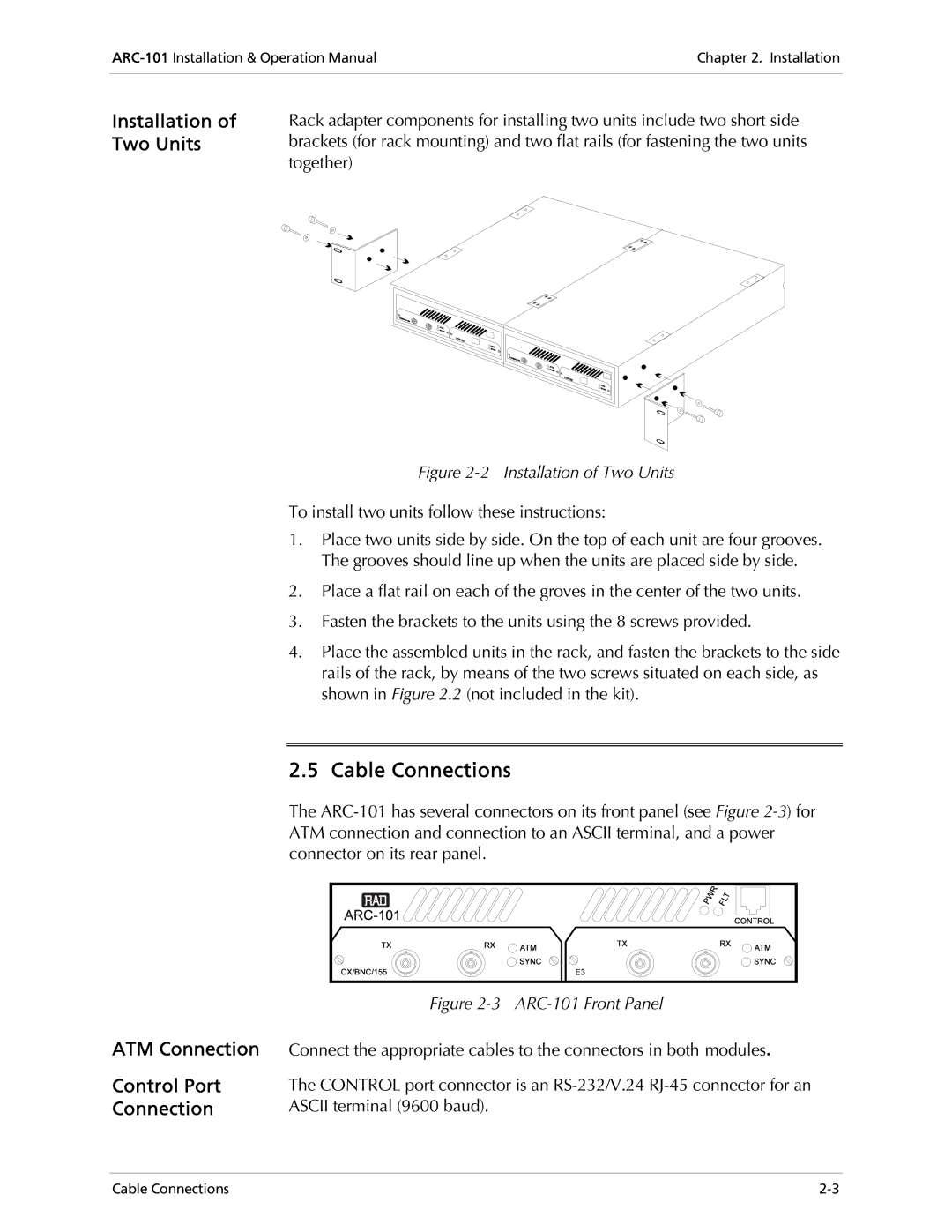
Figure 2-2 Installation of Two Units
To install two units follow these instructions:
1.Place two units side by side. On the top of each unit are four grooves. The grooves should line up when the units are placed side by side.
2.Place a flat rail on each of the groves in the center of the two units.
3.Fasten the brackets to the units using the 8 screws provided.
4.Place the assembled units in the rack, and fasten the brackets to the side rails of the rack, by means of the two screws situated on each side, as shown in Figure 2.2 (not included in the kit).
2.5 Cable Connections
The
ATM Connection
Control Port
Connection
Figure 2-3 ARC-101 Front Panel
Connect the appropriate cables to the connectors in both modules.
The CONTROL port connector is an
Cable Connections |