Chapter 2. Installation | |
|
|
Jumper Settings for T3
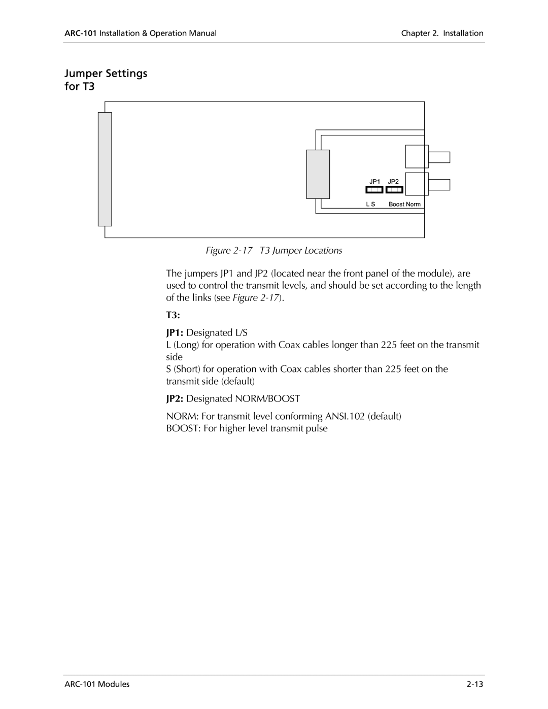
Figure 2-17 T3 Jumper Locations
The jumpers JP1 and JP2 (located near the front panel of the module), are used to control the transmit levels, and should be set according to the length of the links (see Figure
T3:
JP1: Designated L/S
L (Long) for operation with Coax cables longer than 225 feet on the transmit side
S (Short) for operation with Coax cables shorter than 225 feet on the transmit side (default)
JP2: Designated NORM/BOOST
NORM: For transmit level conforming ANSI.102 (default)
BOOST: For higher level transmit pulse
