Chapter 1. Introduction | |
|
|
Ordering ARC-101/#
ATM Rate Converter
#Specify power supply: AC for
ARC-M/@
Interface module for
@ Specify module name - see tables below
RM-1
Hardware for mounting one unit in a 19" rack.
RM-2
Hardware mounting for two units in a 19" rack.
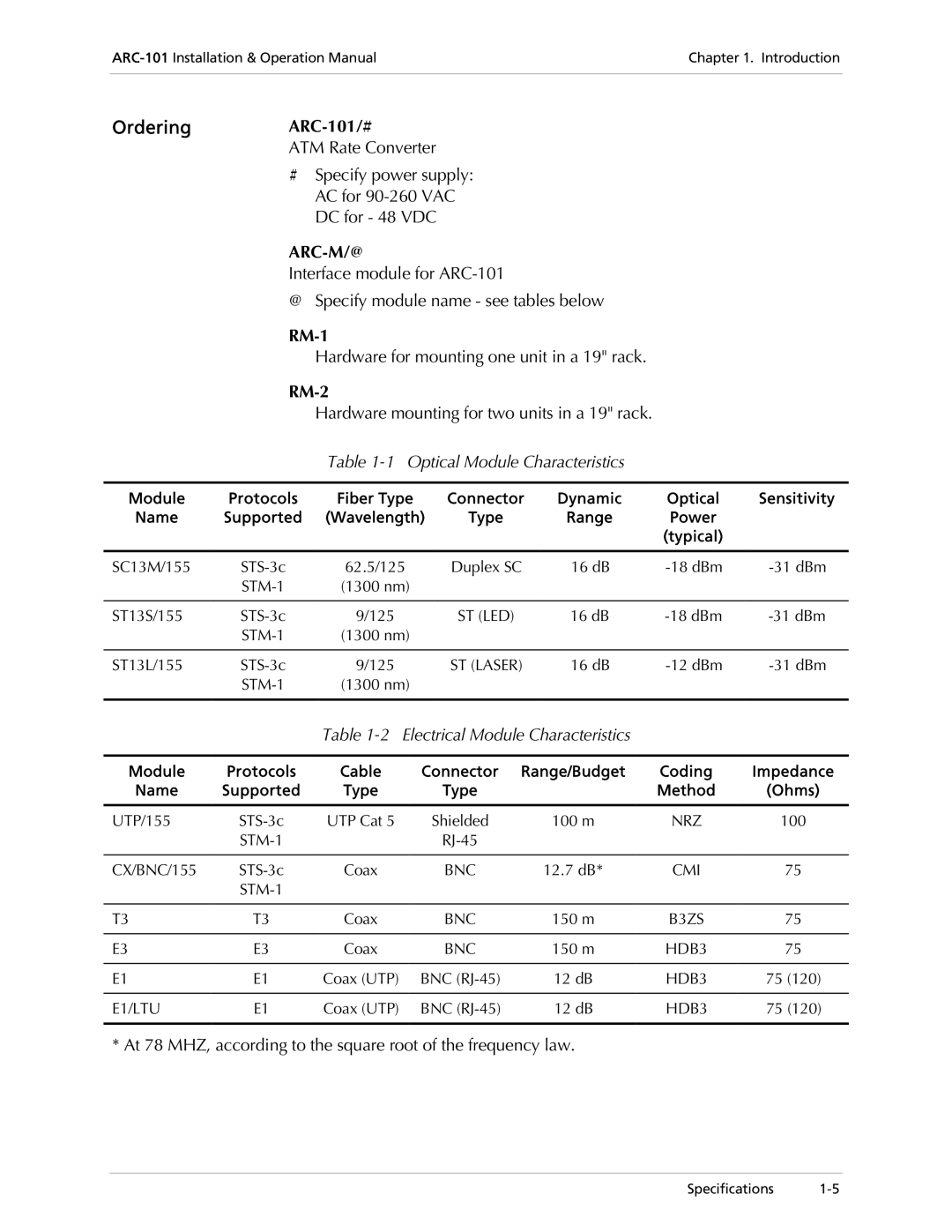
Table 1-1 Optical Module Characteristics
Module | Protocols | Fiber Type | Connector | Dynamic | Optical | Sensitivity |
Name | Supported | (Wavelength) | Type | Range | Power |
|
|
|
|
|
| (typical) |
|
|
|
|
|
|
|
|
SC13M/155 | 62.5/125 | Duplex SC | 16 dB | |||
| (1300 nm) |
|
|
|
| |
|
|
|
|
|
|
|
ST13S/155 | 9/125 | ST (LED) | 16 dB | |||
| (1300 nm) |
|
|
|
| |
|
|
|
|
|
|
|
ST13L/155 | 9/125 | ST (LASER) | 16 dB | |||
| (1300 nm) |
|
|
|
| |
|
|
|
|
|
|
|
Table 1-2 Electrical Module Characteristics
Module | Protocols | Cable | Connector | Range/Budget | Coding | Impedance |
Name | Supported | Type | Type |
| Method | (Ohms) |
|
|
|
|
|
|
|
UTP/155 | UTP Cat 5 | Shielded | 100 m | NRZ | 100 | |
|
|
|
|
| ||
|
|
|
|
|
|
|
CX/BNC/155 | Coax | BNC | 12.7 dB* | CMI | 75 | |
|
|
|
|
|
| |
|
|
|
|
|
|
|
T3 | T3 | Coax | BNC | 150 m | B3ZS | 75 |
|
|
|
|
|
|
|
E3 | E3 | Coax | BNC | 150 m | HDB3 | 75 |
|
|
|
|
|
|
|
E1 | E1 | Coax (UTP) | BNC | 12 dB | HDB3 | 75 (120) |
|
|
|
|
|
|
|
E1/LTU | E1 | Coax (UTP) | BNC | 12 dB | HDB3 | 75 (120) |
|
|
|
|
|
|
|
* At 78 MHZ, according to the square root of the frequency law.
Specifications
