Chapter 2. Installation | |
|
|
Changing
Control Port Mode
When the
Pinout | DCE | DTE |
|
|
|
Pin 1 |
|
|
|
|
|
Pin 2 |
|
|
|
|
|
Pin 3 |
| DTR |
|
|
|
Pin 4 | GND | GND |
|
|
|
Pin 5 | TX Data | RX Data |
|
|
|
Pin 6 | RX Data | TX Data |
|
|
|
Pin 7 |
| CTS |
|
|
|
Pin 8 |
|
|
|
|
|
Pin 9 |
| RTS |
|
|
|
The
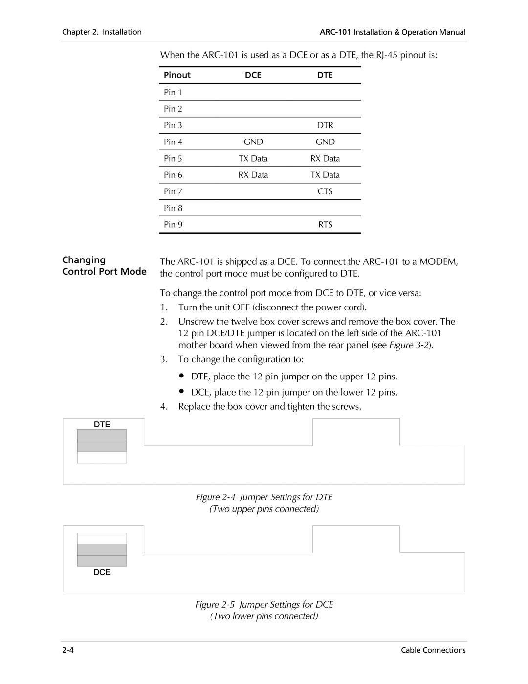
To change the control port mode from DCE to DTE, or vice versa:
1.Turn the unit OFF (disconnect the power cord).
2.Unscrew the twelve box cover screws and remove the box cover. The 12 pin DCE/DTE jumper is located on the left side of the
3.To change the configuration to:
∙DTE, place the 12 pin jumper on the upper 12 pins.
∙DCE, place the 12 pin jumper on the lower 12 pins.
4.Replace the box cover and tighten the screws.
Figure 2-4 Jumper Settings for DTE
(Two upper pins connected)
Figure 2-5 Jumper Settings for DCE
(Two lower pins connected)
Cable Connections |