Chapter 1 Introduction | MBE Family Installation and Operation Manual |
|
|
Link Interface
V.35/V.24
X.21/
4W, ISDN
Power |
Supply |
Main
Processor
and
Communication
Processor
2MB
DRAM
LAN |
| LAN |
Processor |
| Interface |
| Filtering | (not applicable |
ERRORS | Block | to |
LINK |
|
|
ERRORS | MAIN/REM | |
LAN | ||
LINK Rx | Switch |
|
LINK Tx
LAN Rx
LAN Tx
READY
MAIN
LAN
CONN
AUI
BNC
UTP
Async
Port
REMOTE
POWER
Control
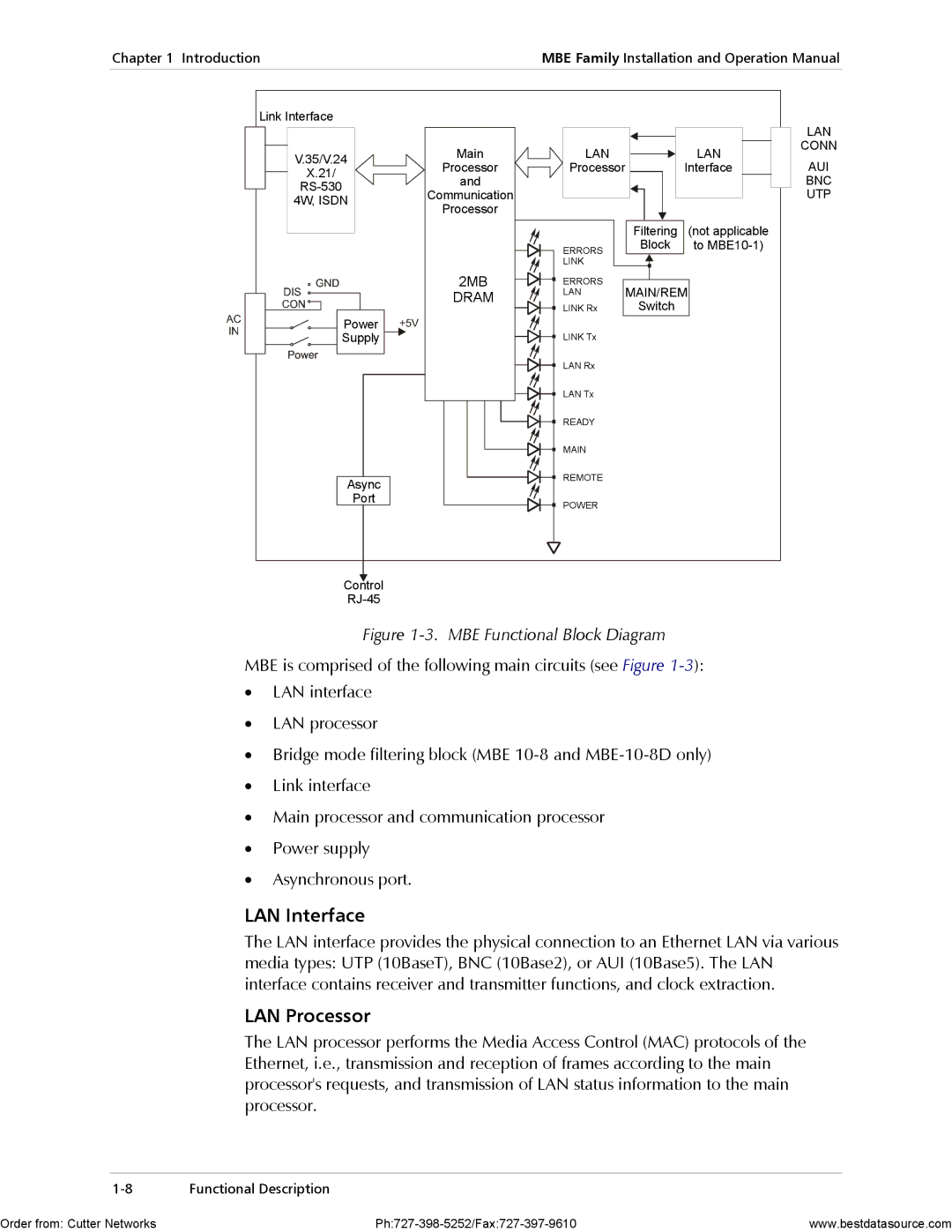
Figure 1-3. MBE Functional Block Diagram
MBE is comprised of the following main circuits (see Figure
•LAN interface
•LAN processor
•Bridge mode filtering block (MBE
•Link interface
•Main processor and communication processor
•Power supply
•Asynchronous port.
LAN Interface
The LAN interface provides the physical connection to an Ethernet LAN via various media types: UTP (10BaseT), BNC (10Base2), or AUI (10Base5). The LAN interface contains receiver and transmitter functions, and clock extraction.
LAN Processor
The LAN processor performs the Media Access Control (MAC) protocols of the Ethernet, i.e., transmission and reception of frames according to the main processor's requests, and transmission of LAN status information to the main processor.
Functional Description |
Order from: Cutter Networks | www.bestdatasource.com |