MBE Family Installation and Operation Manual | Chapter 2 Installation |
|
|
DTE
DCE
DTE/DCE
Jumper
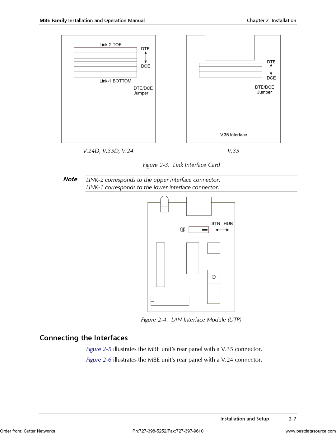
V.24D, V.35D, V.24
DTE |
DCE |
DTE/DCE |
Jumper |
V.35 Interface |
V.35 |
| Figure |
Note |
|
| |
|
|
STN | HUB |
6 |
|
Figure 2-4. LAN Interface Module (UTP)
Connecting the Interfaces
Figure 2-5 illustrates the MBE unit’s rear panel with a V.35 connector.
Figure 2-6 illustrates the MBE unit’s rear panel with a V.24 connector.
Installation and Setup |
Order from: Cutter Networks | www.bestdatasource.com |