MBE Family Installation and Operation ManualChapter 2 Installation
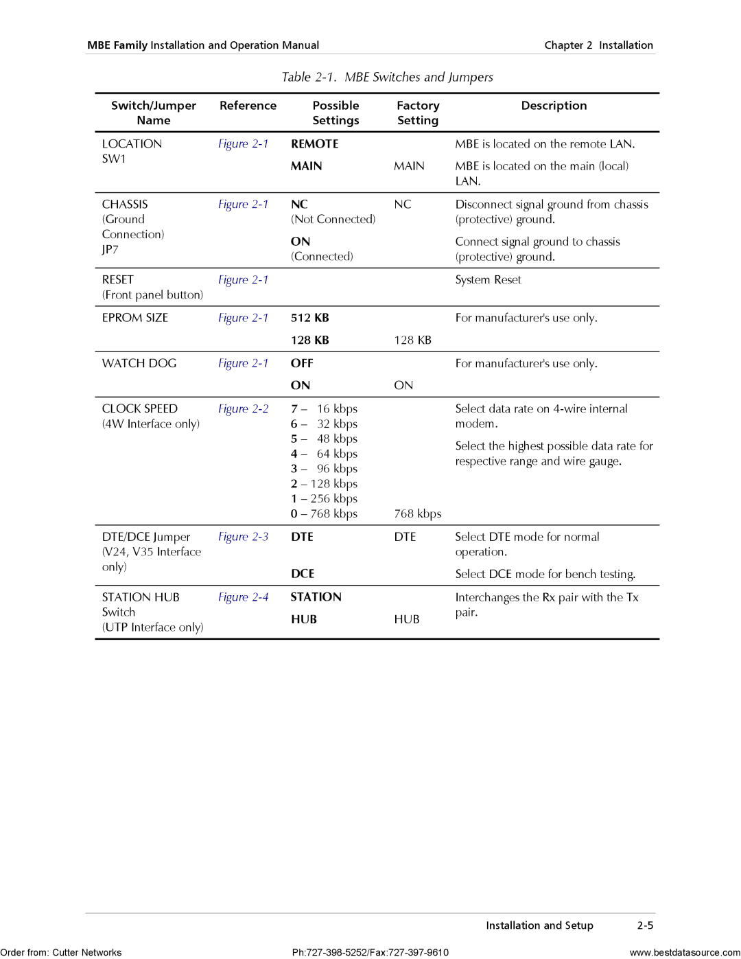
Table 2-1. MBE Switches and Jumpers
Switch/Jumper | Reference | Possible | Factory | Description |
Name |
| Settings | Setting |
|
|
|
|
|
|
LOCATION | Figure | REMOTE |
| MBE is located on the remote LAN. |
SW1 |
| MAIN | MAIN | MBE is located on the main (local) |
|
| |||
|
|
|
| LAN. |
|
|
|
|
|
CHASSIS | Figure | NC | NC | Disconnect signal ground from chassis |
(Ground |
| (Not Connected) |
| (protective) ground. |
Connection) |
| ON |
| Connect signal ground to chassis |
JP7 |
|
| ||
| (Connected) |
| (protective) ground. | |
|
|
| ||
|
|
|
|
|
RESET | Figure |
|
| System Reset |
(Front panel button) |
|
|
|
|
|
|
|
|
|
EPROM SIZE | Figure | 512 KB |
| For manufacturer's use only. |
|
| 128 KB | 128 KB |
|
|
|
|
|
|
WATCH DOG | Figure | OFF |
| For manufacturer's use only. |
|
| ON | ON |
|
CLOCK SPEED | Figure | 7 – | 16 kbps |
| |
(4W Interface only) |
| 6 – | 32 kbps |
| |
|
| 5 | – | 48 kbps |
|
|
| 4 | – | 64 kbps |
|
|
| 3 | – | 96 kbps |
|
|
| 2 | – 128 kbps |
| |
|
| 1 | – 256 kbps |
| |
|
| 0 | – 768 kbps | 768 kbps | |
Select data rate on
Select the highest possible data rate for respective range and wire gauge.
DTE/DCE Jumper | Figure | DTE | DTE | Select DTE mode for normal |
(V24, V35 Interface |
|
|
| operation. |
only) |
| DCE |
| Select DCE mode for bench testing. |
|
|
| ||
|
|
|
|
|
STATION HUB | Figure | STATION |
| Interchanges the Rx pair with the Tx |
Switch |
| HUB | HUB | pair. |
(UTP Interface only) |
|
| ||
|
|
|
| |
|
|
|
|
|
Installation and Setup |
Order from: Cutter Networks | www.bestdatasource.com |