Appendix A
Pin Assignment
This appendix:
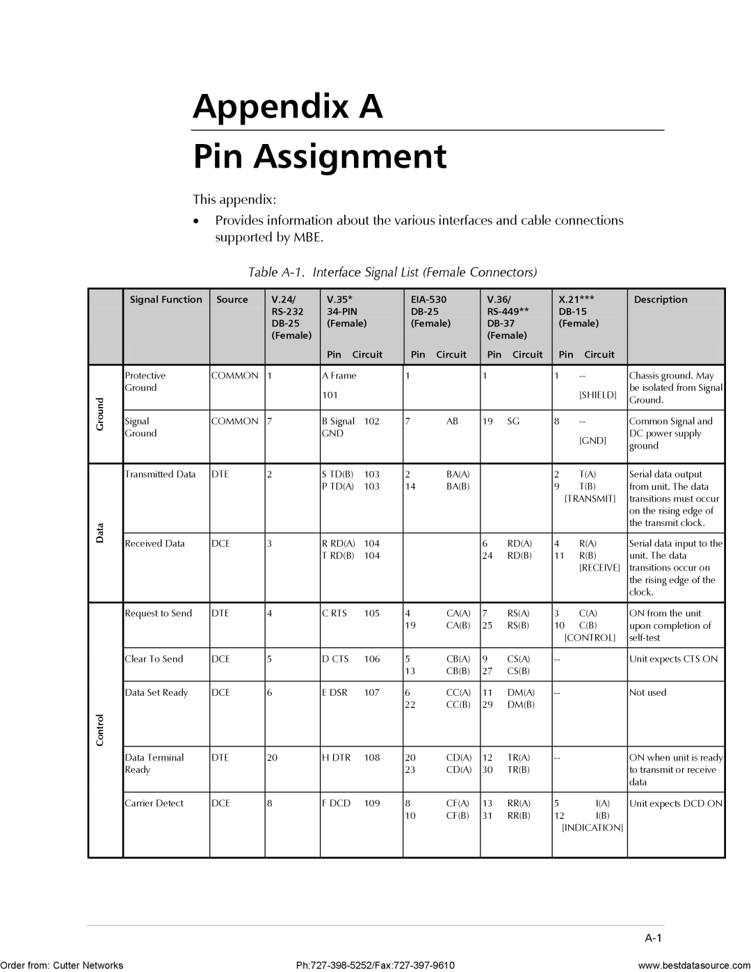
•Provides information about the various interfaces and cable connections supported by MBE.
Table A-1. Interface Signal List (Female Connectors)
| Signal Function | Source | V.24/ |
| V.35* |
| V.36/ | X.21*** | Description | ||||
|
|
|
|
|
| ||||||||
|
|
|
| (Female) | (Female) | (Female) |
| ||||||
|
|
| (Female) |
|
|
|
|
| (Female) |
|
|
| |
|
|
|
|
| Pin Circuit | Pin | Circuit | Pin | Circuit | Pin | Circuit |
| |
|
|
|
|
|
|
|
|
|
|
|
|
|
|
| Protective | COMMON | 1 |
| A Frame |
| 1 |
| 1 |
| 1 | Chassis ground. May | |
| Ground |
|
|
| 101 |
|
|
|
|
|
| [SHIELD] | be isolated from Signal |
Ground |
|
|
|
|
|
|
|
|
|
| Ground. | ||
|
|
|
|
|
|
|
|
|
|
|
| ||
|
|
|
|
|
|
|
|
|
|
|
|
| |
Signal | COMMON | 7 |
| B Signal | 102 | 7 | AB | 19 | SG | 8 | Common Signal and | ||
|
| ||||||||||||
| Ground |
|
|
| GND |
|
|
|
|
|
| [GND] | DC power supply |
|
|
|
|
|
|
|
|
|
|
|
| ground | |
|
|
|
|
|
|
|
|
|
|
|
|
| |
|
|
|
|
|
|
|
|
|
|
|
|
|
|
| Transmitted Data | DTE | 2 |
| S TD(B) | 103 | 2 | BA(A) |
|
| 2 | T(A) | Serial data output |
|
|
|
|
| P TD(A) | 103 | 14 | BA(B) |
|
| 9 | T(B) | from unit. The data |
|
|
|
|
|
|
|
|
|
|
| [TRANSMIT] | transitions must occur | |
|
|
|
|
|
|
|
|
|
|
|
|
| on the rising edge of |
Data |
|
|
|
|
|
|
|
|
|
|
|
| the transmit clock. |
|
|
|
|
|
|
|
|
|
|
|
|
| |
Received Data | DCE | 3 |
| R RD(A) | 104 |
|
| 6 | RD(A) | 4 | R(A) | Serial data input to the | |
|
|
|
| ||||||||||
|
|
|
|
| T RD(B) | 104 |
|
| 24 | RD(B) | 11 | R(B) | unit. The data |
|
|
|
|
|
|
|
|
|
|
|
| [RECEIVE] | transitions occur on |
|
|
|
|
|
|
|
|
|
|
|
|
| the rising edge of the |
|
|
|
|
|
|
|
|
|
|
|
|
| clock. |
|
|
|
|
|
|
|
|
|
|
|
|
|
|
| Request to Send | DTE | 4 |
| C RTS | 105 | 4 | CA(A) | 7 | RS(A) | 3 | C(A) | ON from the unit |
|
|
|
|
|
|
| 19 | CA(B) | 25 | RS(B) | 10 | C(B) | upon completion of |
|
|
|
|
|
|
|
|
|
|
| [CONTROL] | ||
|
|
|
|
|
|
|
|
|
|
|
|
|
|
| Clear To Send | DCE | 5 |
| D CTS | 106 | 5 | CB(A) | 9 | CS(A) |
| Unit expects CTS ON | |
|
|
|
|
|
|
| 13 | CB(B) | 27 | CS(B) |
|
|
|
|
|
|
|
|
|
|
|
|
|
|
|
|
|
| Data Set Ready | DCE | 6 |
| E DSR | 107 | 6 | CC(A) | 11 | DM(A) |
| Not used | |
|
|
|
|
|
|
| 22 | CC(B) | 29 | DM(B) |
|
|
|
Control |
|
|
|
|
|
|
|
|
|
|
|
|
|
| Data Terminal | DTE | 20 |
| H DTR | 108 | 20 | CD(A) | 12 | TR(A) |
| ON when unit is ready | |
| Ready |
|
|
|
|
| 23 | CD(A) | 30 | TR(B) |
|
| to transmit or receive |
|
|
|
|
|
|
|
|
|
|
|
|
| data |
|
|
|
|
|
|
|
|
|
|
|
|
|
|
| Carrier Detect | DCE | 8 |
| F DCD | 109 | 8 | CF(A) | 13 | RR(A) | 5 | I(A) | Unit expects DCD ON |
|
|
|
|
|
|
| 10 | CF(B) | 31 | RR(B) | 12 | I(B) |
|
|
|
|
|
|
|
|
|
|
|
| [INDICATION] |
| |
|
|
|
|
|
|
|
|
|
|
|
|
|
|
Order from: Cutter Networks | www.bestdatasource.com |