Chapter 3
Operation
This chapter:
•Describes MBE front panel controls and indicators
•Provides basic operation instructions.
For
Configuration Guide.
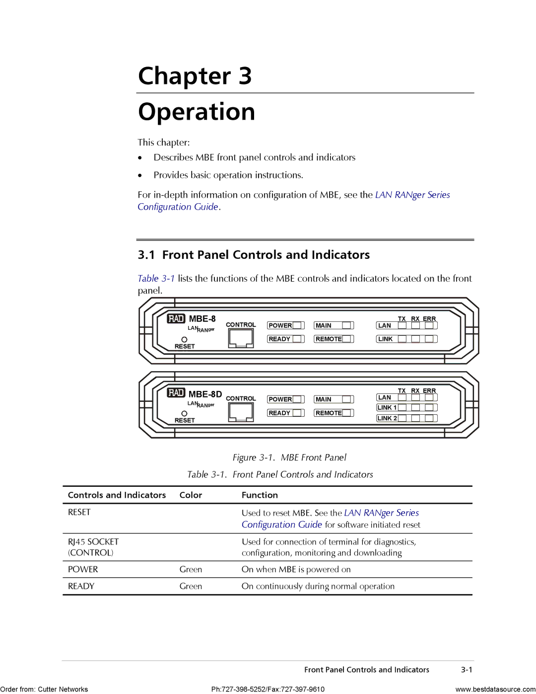
3.1 Front Panel Controls and Indicators
Table
CONTROL | POWER | MAIN | TX RX ERR | |
LAN | ||||
LANRANger |
|
|
|
|
|
| READY | REMOTE | LINK |
RESET
|
| TX | RX ERR | |
POWER | MAIN | LAN |
| |
LANRANger | READY | REMOTE | LINK 1 |
|
RESET | LINK 2 |
| ||
|
|
|
|
| Figure |
| Table | |
|
|
|
Controls and Indicators | Color | Function |
|
|
|
RESET |
| Used to reset MBE. See the LAN RANger Series |
|
| Configuration Guide for software initiated reset |
|
|
|
RJ45 SOCKET |
| Used for connection of terminal for diagnostics, |
(CONTROL) |
| configuration, monitoring and downloading |
|
|
|
POWER | Green | On when MBE is powered on |
|
|
|
READY | Green | On continuously during normal operation |
|
|
|
| Front Panel Controls and Indicators | |
Order from: Cutter Networks | www.bestdatasource.com |