Appendix A Pin AssignmentMBE Family Installation and Operation Manual
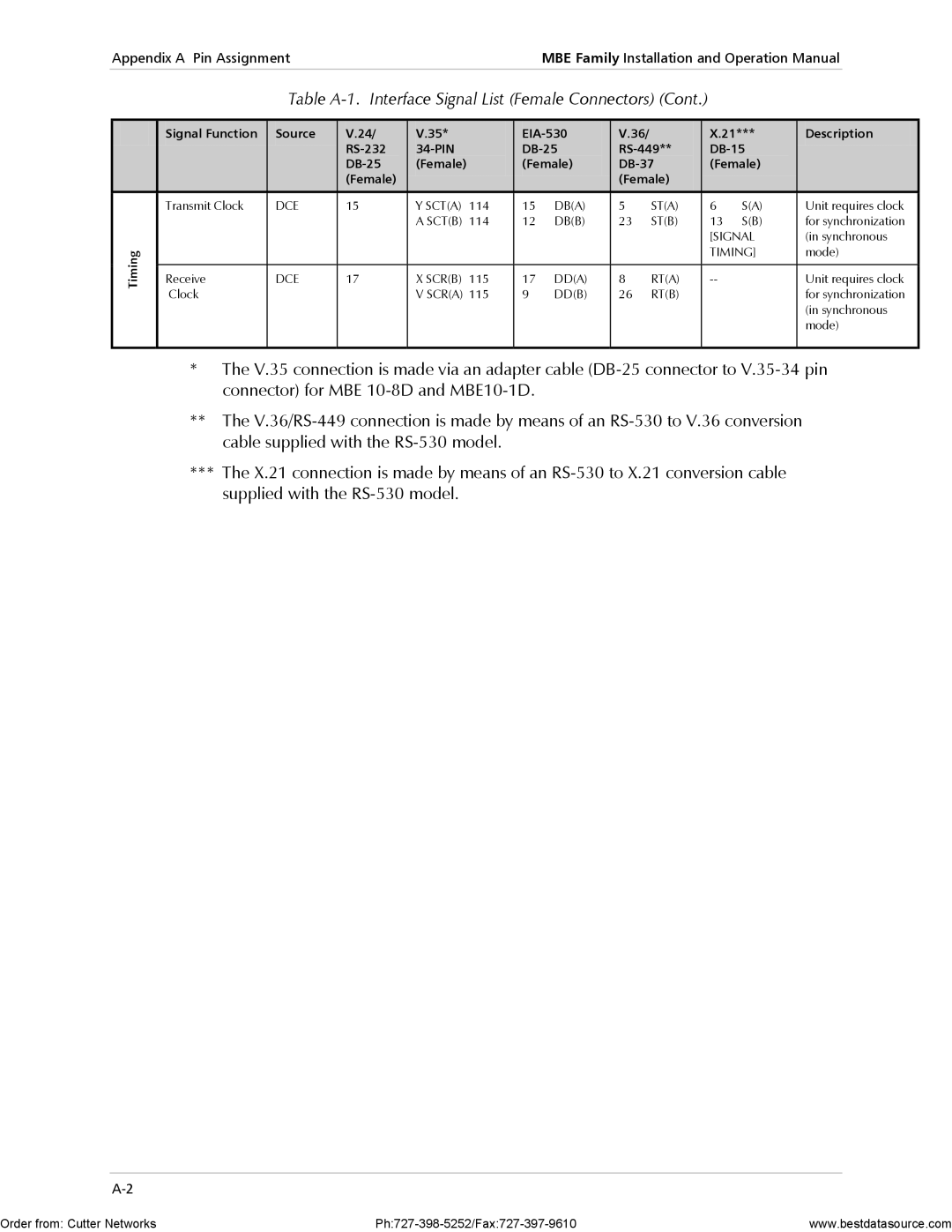
Table A-1. Interface Signal List (Female Connectors) (Cont.)
| Signal Function | Source | V.24/ | V.35* |
| V.36/ |
| X.21*** | Description | |||
|
|
|
|
| ||||||||
|
|
| (Female) |
| (Female) |
| (Female) |
| ||||
|
|
| (Female) |
|
|
|
| (Female) |
|
|
| |
|
|
|
|
|
|
|
|
|
|
|
|
|
| Transmit Clock | DCE | 15 | Y SCT(A) | 114 | 15 | DB(A) | 5 | ST(A) | 6 | S(A) | Unit requires clock |
|
|
|
| A SCT(B) | 114 | 12 | DB(B) | 23 | ST(B) | 13 | S(B) | for synchronization |
|
|
|
|
|
|
|
|
|
| [SIGNAL | (in synchronous | |
Timing |
|
|
|
|
|
|
|
|
| TIMING] | mode) | |
|
|
|
|
|
|
|
|
|
|
|
| |
Receive | DCE | 17 | X SCR(B) | 115 | 17 | DD(A) | 8 | RT(A) |
| Unit requires clock | ||
|
| |||||||||||
| Clock |
|
| V SCR(A) 115 | 9 | DD(B) | 26 | RT(B) |
|
| for synchronization | |
|
|
|
|
|
|
|
|
|
|
|
| (in synchronous |
|
|
|
|
|
|
|
|
|
|
|
| mode) |
|
|
|
|
|
|
|
|
|
|
|
|
|
*The V.35 connection is made via an adapter cable
**The
***The X.21 connection is made by means of an
Order from: Cutter Networks | www.bestdatasource.com |