SETUP AND CONNECTIONS
BASIC CONNECTION USING A MULTIMEDIA OR HD MONITOR
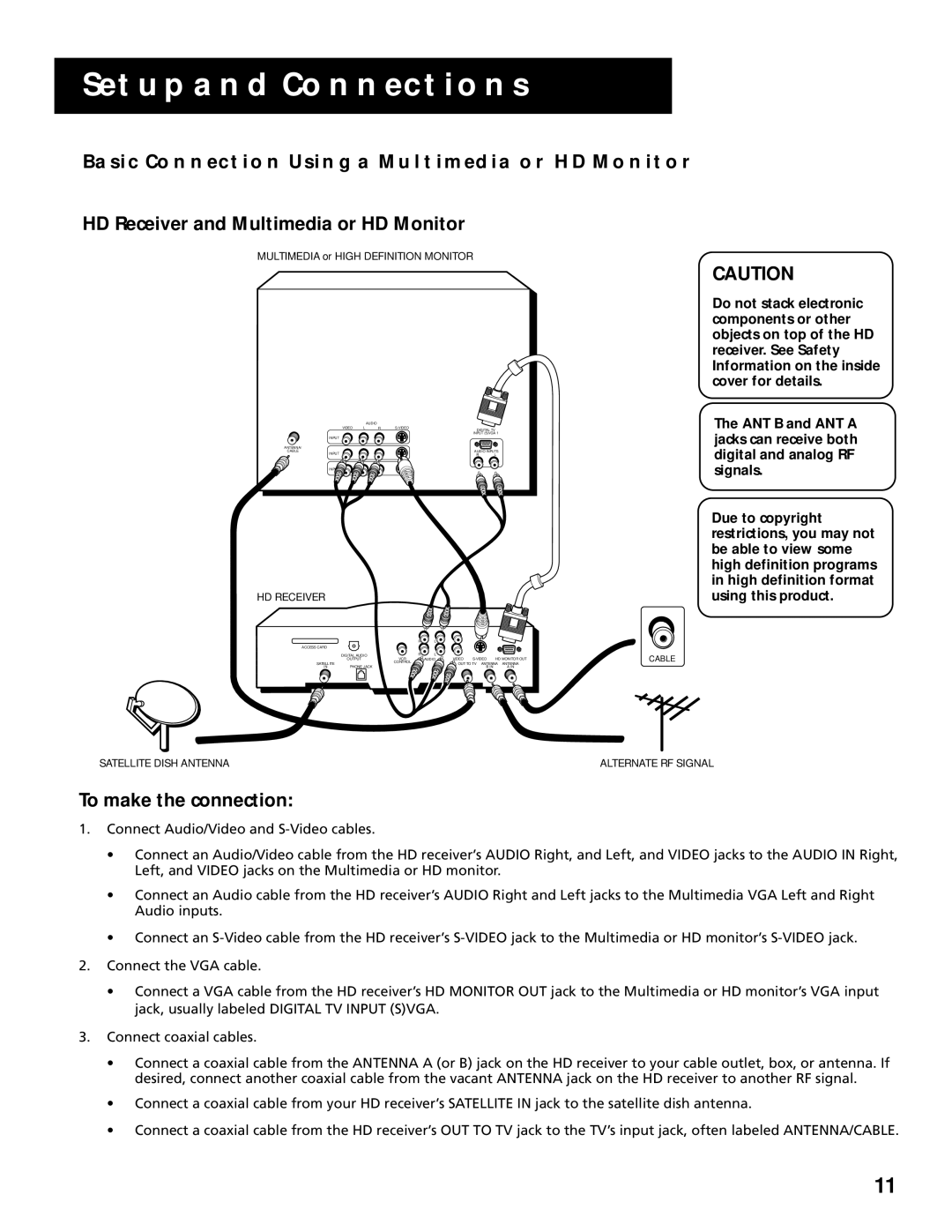
HD Receiver and Multimedia or HD Monitor
MULTIMEDIA or HIGH DEFINITION MONITOR
CAUTION
|
| AUDIO |
|
|
VIDEO | L | R |
| |
|
|
| DIGITAL TV | |
|
|
| INPUT (5)VGA 1 | |
INPUT |
|
|
|
|
ANTENNA/ |
|
|
|
|
CABLE |
|
| AUDIO INPUTS | |
INPUT |
|
| R | L |
INPUT
HD RECEIVER
|
| R | L |
|
|
|
ACCESS CARD |
|
|
|
|
|
|
| DIGITAL AUDIO | R | L |
|
|
|
| OUTPUT | VCR | AUDIO | VIDEO | HD MONITOR OUT | |
SATELLITE |
| CONTROL |
| OUT TO TV ANTENNA ANTENNA | ||
IN | PHONE JACK |
|
|
| B IN | A IN |
SATELLITE DISH ANTENNA
Do not stack electronic components or other objects on top of the HD receiver. See Safety Information on the inside cover for details.
The ANT B and ANT A jacks can receive both digital and analog RF signals.
Due to copyright restrictions, you may not be able to view some high definition programs in high definition format using this product.
CABLE
ALTERNATE RF SIGNAL
To make the connection:
1.Connect Audio/Video and
•Connect an Audio/Video cable from the HD receiver’s AUDIO Right, and Left, and VIDEO jacks to the AUDIO IN Right, Left, and VIDEO jacks on the Multimedia or HD monitor.
•Connect an Audio cable from the HD receiver’s AUDIO Right and Left jacks to the Multimedia VGA Left and Right Audio inputs.
•Connect an
2.Connect the VGA cable.
•Connect a VGA cable from the HD receiver’s HD MONITOR OUT jack to the Multimedia or HD monitor’s VGA input jack, usually labeled DIGITAL TV INPUT (S)VGA.
3.Connect coaxial cables.
•Connect a coaxial cable from the ANTENNA A (or B) jack on the HD receiver to your cable outlet, box, or antenna. If desired, connect another coaxial cable from the vacant ANTENNA jack on the HD receiver to another RF signal.
•Connect a coaxial cable from your HD receiver’s SATELLITE IN jack to the satellite dish antenna.
•Connect a coaxial cable from the HD receiver’s OUT TO TV jack to the TV’s input jack, often labeled ANTENNA/CABLE.
11