INSTALLATION

INSTALLING THE OPTIONAL FAN

120 Volt AC power is needed for the fan switch and blower. The fan can be hard wired if desired. The receptacleboxshouldbeinstalled on theleft handsideoftheunitbyaqualifiedelectrician.The neutral (wider) slot of the polarized receptacle should be at the top.

Unit must be grounded at all times. Do not cut the ground terminal off under any circumstances.

1)Shut the power off.

2)Remove the standard fl ush door and the optional bay door, if installed. Open the bottom louver door.

3)Remove the 2 screws holding the Burner ON/OFF switch and bracket to the bottom louver and lift the assembly out.

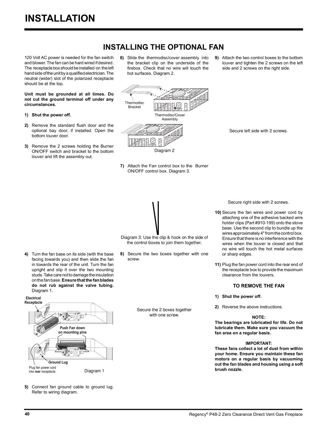
6) Slide the thermodisc/cover assembly into

9) Attach the two control boxes to the bottom

the bracket clip on the underside of the

louver and tighten the 2 screws on the left

fi rebox. Check that no wire will touch the

side and 2 screws on the right side.

hot surfaces. Diagram 2.


Secure left side with 2 screws.

Diagram 2

7)Attach the Fan control box to the Burner ON/OFF control box. Diagram 3.

4)Turn the fan base on its side (with the base facing towards you) and then slide the fan in towards the rear of the unit. Turn the fan upright and slip it over the two mounting studs.Takecarenottodamagetheinsulation on the fan base. Ensure that the fan blades do not rub against the valve tubing. Diagram 1.

Diagram 1

5)Connect fan ground cable to ground lug. Refer to wiring diagram.

Diagram 3: Use the clip & hook on the side of

the control boxes to join them together.

8)Secure the two boxes together with one screw.

Secure the 2 boxes together

with one screw.

Secure right side with 2 screws.

10)Secure the fan wires and power cord by attaching one of the adhesive backed wire holder clips (Part #910-199) onto the stove base. Use the second clip to bundle up the wires approximately 4" from the control box. Ensure that there is no interference with the wires when the louver is closed and that no wire will touch the hot metal surfaces or sharp edges.

11)Plug the fan power cord into the rear end of the receptacle box to provide the maximum clearance from the louvers.

TO REMOVE THE FAN

1)Shut the power off.

2)Reverse the above instructions.

NOTE:

The bearings are lubricated for life. Do not lubricate them. Make sure you vacuum the fan area on a regular basis.

IMPORTANT:

These fans collect a lot of dust from within your home. Ensure you maintain these fan motors on a regular basis by vacuuming out the fan blades and housing using a soft brush nozzle.

40

Regency® P48-2 Zero Clearance Direct Vent Gas Fireplace

Page 40
Image 40
Regency P48-2 installation manual Installing the Optional FAN, Secure left side with 2 screws Diagram

P48-2 specifications

The Regency P48-2 is an advanced handheld radio transceiver that has gained recognition among amateur radio enthusiasts for its remarkable features, performance, and cutting-edge technology. This compact device offers a perfect combination of versatility and ease of use, making it suitable for both beginners and experienced operators.

One of the standout characteristics of the P48-2 is its robust communication capabilities. Operating in the VHF and UHF frequency ranges, this transceiver can effortlessly handle a variety of communication modes including FM, SSB, and CW. This versatility allows users to engage in a wide range of activities, from casual chatting to serious emergency communications.

The P48-2 is equipped with a powerful microprocessor that facilitates efficient signal processing, resulting in clearer audio and reduced interference. This advanced technology enhances the user experience significantly, particularly in crowded bands. Additionally, the built-in Automatic Frequency Control (AFC) helps maintain frequency stability, especially important when operating in dynamic environments.

Another notable feature of the P48-2 is its ergonomic design. Weighing less than many competitors in its class, it boasts a lightweight yet durable construction. Its intuitive interface, complete with a large LCD screen, makes navigation seamless. Users can easily adjust settings, frequency selections, and access various functions without any hassle, even during field operations.

Battery life is also impressive, with the P48-2 designed to handle long operational hours without the need for frequent recharging. This is particularly beneficial for outdoor enthusiasts and those who require reliable communication during extended trips. The device is compatible with a range of rechargeable batteries, providing flexibility for users to choose their preferred power source.

In addition to its core functionalities, the Regency P48-2 comes with a range of accessories that enhance its overall usability. Optional external microphones, headsets, and antenna models can be integrated to optimize communication quality. This adaptability ensures that users can customize their experience to suit specific needs.

Finally, the P48-2 is backed by robust customer support and a thriving community of users. This network of fellow operators often shares tips, modifications, and troubleshooting advice, creating a collaborative environment for newcomers and experts alike.

In summary, the Regency P48-2 is a highly capable transceiver that offers exceptional performance, user-friendly design, and versatile communication options. Its advanced technologies and robust features make it a standout choice for anyone looking to explore the world of amateur radio. Whether for casual use or emergency situations, the Regency P48-2 proves to be a reliable companion.