DIGITAL AND OPTO PORTS
INTRODUCTION
Digital I/ O lines ar e used to inter face with op
Eight lines at P6 are intended for general purpose TTL I/O such as switches, level sensors or to drive other devices.
A 24 line con nector, J3, is inte nded to inter face to opto racks or other TT L devices. 8 of these lines are high curr ent outputs, capable of sink ing 75 to 200 m a. O pto modules on an opto rack sense presence of AC or DC voltages or switch them .
L8 at P2 is a "zero" ohm FE T switch. It is intended for switching L ED b ack lighting on a n LC D display. This line may also be used to switch high current, high voltage power . It can sw itch up to 2 amps.
ISOA/B is used as an isolated input as well as an interr upt.
In addition to the 24 I/O lines from J3, the display port can be used as digital I/O . Refer to Chapter 8 for more information.
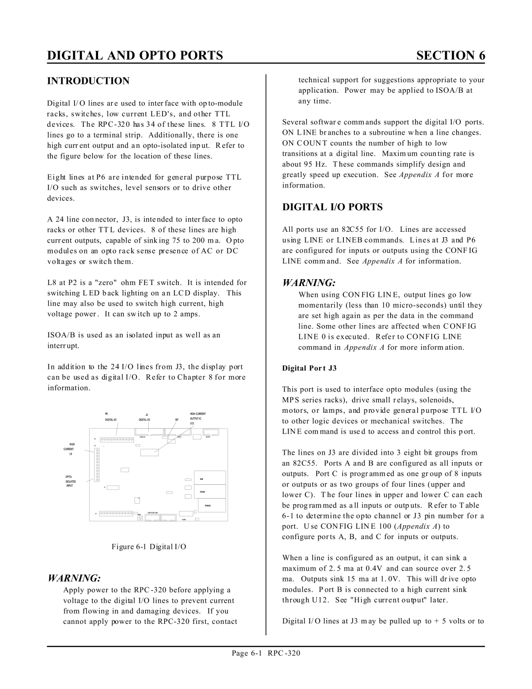
Figure |
WARNING:
Apply power to the RPC
SECTION 6
technical support for suggestions appropriate to your application. Power may be applied to ISOA/B at any time.
Several softwar e comm ands support the digital I/O ports. ON L INE br anches to a subroutine w hen a line changes. ON C OUN T counts the number of high to low transitions at a digital line. Maxim um coun ting rate is about 95 Hz. T hese commands simplify design and greatly speed up execution. See Appendix A for more information.
DIGITAL I/O PORTS
All ports use an 82C55 for I/O. Lines are accessed using LINE or LINEB commands. Lines at J3 and P6 are configured for inputs or outputs using the CONF IG LINE comm and. See Appendix A for information.
WARNING:
When using CON FIG LIN E, output lines go low momentarily (less than 10
Digital Por t J3
This port is used to interface opto modules (using the MP S series racks), drive small r elays, solenoids, motors, or lamps, and provide general purpose TTL I/O to other logic devices or mechanical switches. The LIN E com mand is use d to access an d control this p ort.
The lines on J3 are divided into 3 eight bit groups from an 82C55. Ports A and B are configured as all inputs or outputs. Port C is progr amm ed as one gr oup of 8 inputs or outputs or as two groups of four lines (upper and lower C). T he four lines in upper and lower C can each be prog ram med as a ll inputs or outp uts. R efer to T able
6 - 1 to determine the opto channel or J3 pin number for a port. U se CON FIG LIN E 100 (Appendix A) to configure por ts A, B, and C for inputs or outputs.
When a line is configured as an output, it can sink a maximum of 2. 5 ma at 0.4V and can source over 2. 5 ma. Outputs sink 15 ma at 1. 0V. This will dr ive opto modules. P ort B is connected to a high current sink through U12 . See "High current output" later .
Digital I/ O lines at J3 m ay be pulled up to + 5 volts or to
Page