ANALOG INPUT
DESCRIPTION
The RP
Reference IC U 14 has a voltage output that corresponds to the IC tem peratur e. T his output ma y be used to measure ambient temperature.
Two am plifiers are available to signal condition inputs. By installing appr opriate r esistors and capacitor s, inp uts are buffered, amplified, and filtered.
This chapter begins with basic information on connecting and using ana log inputs. Later , de scriptions of how to measure voltages other than 2 . 5 or 5 volts, temperature measurem ent, data logging, using the amplifiers, and calibration are presented.
CONNECTING ANALOG INPUTS
All analog inputs interface through connector P4. Additional compone nts, such as r esistors and capacitors, may be conne cted directly to the screw terminals.
For gr eatest accuracy, connect unused inputs to ground.
R17 is adjusted to trim accuracy to your system. See Calibration later in this chapter for more information.
Tem peratur e output or other signa l input may g o directly to channel 0 via header H1. See Temperature Measurement and Amplifiers below.
Overvoltage conditions
Inputs are protected over voltage protected. M aximum voltage on 1 channel is 25 volts. M aximum voltage for 2 to 4 channels is 12 volts. Total input current m ay not exceed 16 ma on all channels. Each channels input current is computed by the following formula:
Iin = (Vin - 5)/4700
When V in < 5 volts, no curr ent flows into the channel.
NOTE: An
SECTION 10
usually affects readings on other channels.
Grounding
Analog ground is somewhat isolated from digital ground. While the ground plane is connected between the two, analog ground is a virtual "island" connected only in one place to digital ground. To minimize noise pickup, the sending device should be connected to analog ground (located at the a nalog input ter minal str ip). W hen both analog and digital grounds come from the same device, you will have to play aro und with the g rounds to determine which scheme provides the best performance for your system .
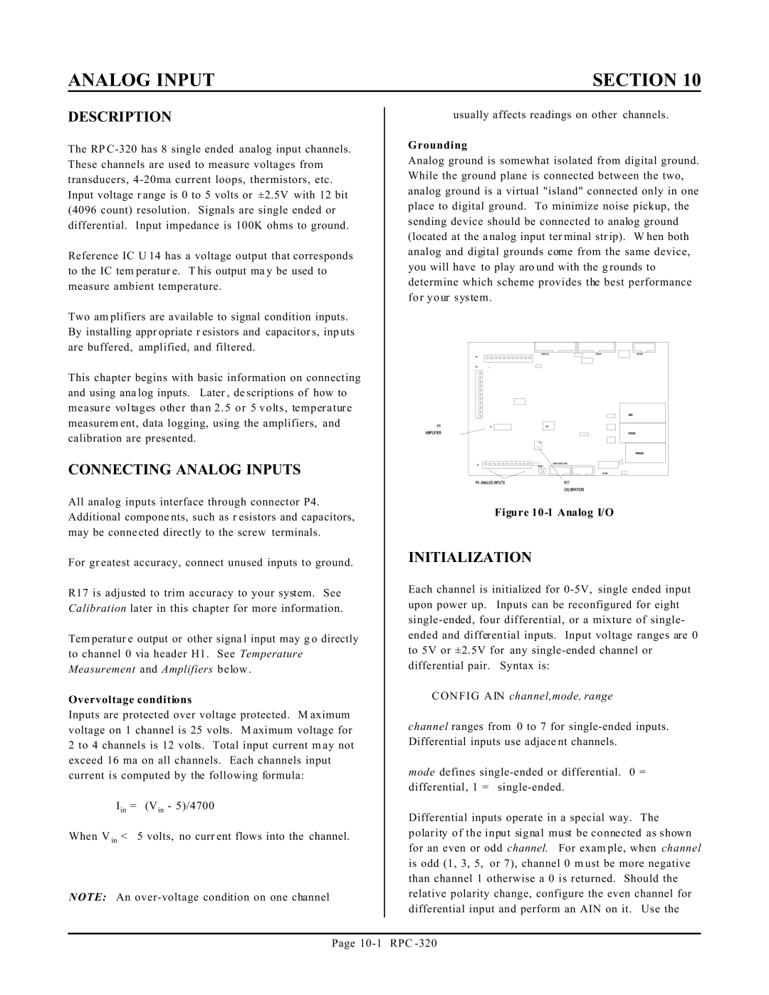
Figure |
INITIALIZATION
Each channel is initialized for
CONFIG AIN channel,mode, range
channel ranges from 0 to 7 for
mode defines
Differential inputs operate in a special way. The polarity of the input signal must be connected as shown for an even or odd channel. For exam ple, when channel is odd (1, 3, 5, or 7), channel 0 m ust be more negative than channel 1 otherwise a 0 is returned. Should the relative polarity change, configure the even channel for differential input and perform an AIN on it. Use the
Page