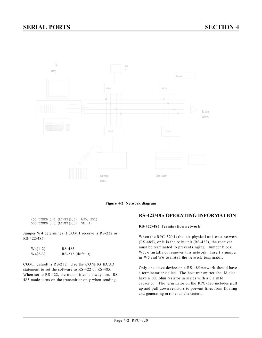
Figure 4-2 Network diagram
400 LINEB 5,0,(LINEB(5,0) .AND. 251)
500 LINEB 5,0,(LINEB(5,0) .OR. 4)
Jumper W 4 determines if COM 1 receive is RS-232 or RS-422/485.
W4[1-2] | RS-485 |
W4[2-3] | RS-232 (de fault) |
COM1 default is RS -232. Use the CONFIG BAUD statement to set the software to RS-422 or RS-485. When set to RS-422, the transm itter is always on. RS- 485 mode turns on the transmitter only when sending.
RS-422/485 OPERATING INFORMATION
RS-422/485 Termination network
When the RPC - 320 is the last physical unit on a network (RS-485), or it is the only unit (RS-422), the receiver must be terminated to prevent ringing. Jumper block W5, 6 installs or removes this network. Insert a jumper in W5 and W6 to install the network terminator .
Only one slave device on a RS-485 network should have a terminator installed. The host transmitter shou ld also have a 100 ohm resistor in series with a 0.1 m fd capacitor . T he term inator on the RPC -320 includes p ull up and pull down resistors to prevent lines from floating and generating er roneous char acters.