ANALOG INPUT
CONVERTING ANALOG
MEASUREMENTS
Inputs are converted to "real numbe rs" by perfor ming scaling calculations in the program. The AIN function returns values from 0 to 4095 . To change these numbers into something more meaningful, use the following formula:
var = K * AIN(n)
n is the analog channel to read. K is the scaling constant. K is obtained by dividing the highest number in the range of units by the maximum AIN count (4095).
Example 1: To measure the results of an A/D conversion in volts and the voltage range is 0 to 5V, divided 5 by 4095 to obtain K.
K = 5/4095
K = .001221
Your program could look something like:
1000 C = .001221 * AIN(N)
Example 2: Y ou want to measure a 0 to 200 PSI pressure transducer w ith a 0 to + 5V output. Divide 200 by 4095 to obtain the constant K.
K = 200 / 4095
K = .0488
The code can then look like:
1000 B = .0488 * AIN(0)
Measuring 4-20 mA current loops
Curr ent loops is a convenient way to transmit a value and still assure the integrity of the signal. If the line should break, a 0 volt (or nearly so) is returned.
A
Cur rent loop r eadings ar e conver ted to engineer ing units by performing scaling as described earlier. Since the measur ement r ange is 1 to 5V , the count ran ge is reduced by 20% to 3276.
If pressure were measured:
SECTION 10
K = 200/3276
K = .06105
There is one addition factor. Since the lowest value read is 1 V, this offset is subtracted from all readings. A 1 V offset is 1/5 of 4095 counts, or 819. The program line then becomes:
200
Note that if the current loop line breaks, a negative value is returned.
AMPLIFIERS
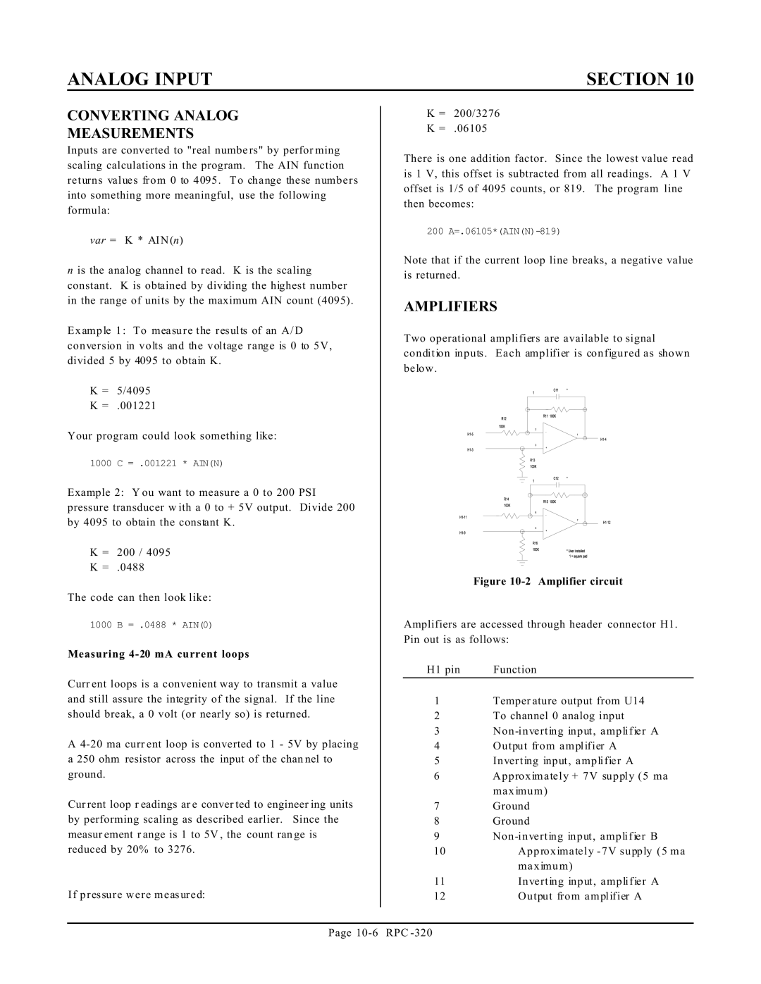
Two operational amplifiers are available to signal condition inputs. Each amplifier is configured as shown below.
Figure 10-2 Amplifier circuit
Amplifiers are accessed through header connector H1. Pin out is as follows:
H1 pin | Function |
1Temper ature output from U14
2To channel 0 analog input
3Non
4Output from amplifier A
5Inverting input, amplifier A
6Approximately + 7V supply (5 ma maximum)
7Ground
8Ground
9Non
10 | Approximately - 7V supply (5 ma |
| maximum) |
11 | Inverting input, amplifier A |
12 | Output from amplifier A |
Page
