Manuals
/
Remote Technologies
/
TV and Video
/
Universal Remote
Remote Technologies
RPC-320
manual
Section
Models:
RPC-320
1
31
51
51
Download
51 pages
34.03 Kb
28
29
30
31
32
33
34
35
Troubleshooting
Specs
Interrupt Characteristics
Data logging on a timer tick
Symbols and Term inology
Two wire RS-485
Config Line
External Reset
Accessing COM0 and COM1
Commands
Page 31
Image 31
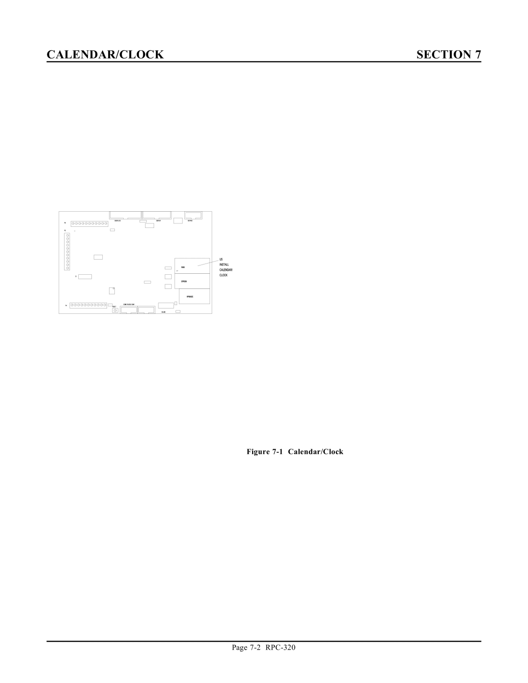
CALENDAR/CLOCK
SECTION 7
Figure
7-1
Calendar/Clock
Page
7-2
RPC-320
Page 30
Page 32
Page 31
Image 31
Page 30
Page 32
Contents
Trademarks
REV
Revision
Table of Contents
Sect ION 13 Multi Mode Counter Description
Sect ION 11 Watchdog Timer Description
External Reset
Interrupt Characteristics
Software Revision History
Manual Organization
Overview
Section
Description
Technical Support
Symbols and Term inology
System layout
Overview Section
Introduction
Operating Precautions
Equipment
Uploading and Downloading Programs
Using a PC
Using a Terminal
First Time Operation
Editing programs and program ming hints
Troubleshooting
Where to GO from Here
W3 autorun jumper
Saving Programs
Saving a Program
Eprom
Changing Eprom Size
Autorunning
Preventing Autorun
Loading a Program
Bsave
Commands
Alternate Eproms
Bload
COM0 Serial Port
Serial Ports
COM1 Serial Port
RS-422/485 Operating Information
Serial Ports Section
RS-422/485 Termination network
Two wire RS-485
Accessing Serial Buffers
Multidrop Network
Disabling CONTROL-C
Accessing COM0 and COM1
Serial Port PIN OUT
RXD CTS
Changing Memory
Battery Backup
Checking the battery
RAM Memory
Storing Variables in RAM
Reserved Memory
Block Data Transfer
Assembly Language Interface
Digital I/O Ports
Digital and Opto Ports
Digital Por t J3
Optically Isolated Input
Digital I/O Commands
Digital Port P6
High Current Port L8
High Current Output
Interfacing Digital I/O to an opto-module rack
Interfacing to switches and other devices
Digital I/ O prog ramm ing exam ple
Ls e Width Modulation PWM
Conne ctor pin ou t J3
Digital and Opto Ports Section
Line B
Config Line
Count
Line
Date
Setting Date and Time
M E
Section
Writing to the Display
Connecting Displays
Programming Example
Display Types
Display Connector PIN OUT
Program explanation
Keypad Port
Keypad Port PIN OUT J5
Overvoltage conditions
Connecting Analog Inputs
Analog Input
Initialization
Examples u sing CON FIG AIN
Differential Mode
Acquiring Analog Data
Noise Notes
Temperature Measurement
Analog Input Section
Measuring Higher Voltages
Data logging on a timer tick
Amplifiers
Converting Analog Measurements
Measuring 4-20 mA current loops
Calibration
External Reset
Watchdog Timer
Optically Isolated Interrupt
Interrupt Characteristics
Program Example
Optically isolated and TTL interrup ts
Gate
Programming
GND
Load
COU NT0
Further Power Reduction
Power Management
Program Examp le
Power Management Section
Technical Information
Electrical Specifications
Bank
Mechanical Specifications
Memory and I/O Bank MAP
Jumper Descriptions
Top
Page
Image
Contents