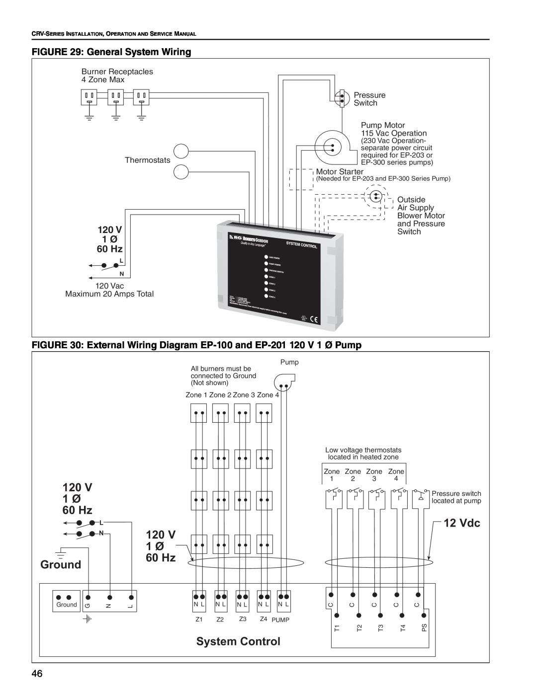
FIGURE 29: General System Wiring
Burner Receptacles 4 Zone Max
Thermostats
120 V |
1 Ø |
60 Hz |
L |
N |
120Vac
Maximum 20 Amps Total
Pressure
Switch
Pump Motor
115 Vac Operation
(230 Vac Operation- separate power circuit required for
![]() Motor Starter
Motor Starter
(Needed for
Outside
Air Supply
Blower Motor
and Pressure
Switch
FIGURE 30: External Wiring Diagram |
|
|
| |||||||||
|
|
| All burners must be |
| Pump |
|
|
|
|
| ||
|
|
|
|
|
|
|
|
|
| |||
|
|
| connected to Ground |
|
|
|
|
|
|
| ||
|
|
| (Not shown) |
|
|
|
|
|
|
|
| |
|
|
| Zone 1 Zone 2 Zone 3 Zone 4 |
|
|
|
|
| ||||
|
|
|
|
|
|
|
| Low voltage thermostats |
| |||
|
|
|
|
|
|
|
| located in heated zone |
| |||
|
|
|
|
|
|
|
| Zone Zone | Zone | Zone |
| |
120 V |
|
|
|
|
|
|
| 1 | 2 | 3 | 4 |
|
|
|
|
|
|
|
|
|
|
|
| Pressure switch | |
1 Ø |
|
|
|
|
|
|
|
|
|
|
| |
|
|
|
|
|
|
|
|
|
|
| located at pump | |
60 Hz |
|
|
|
|
|
|
|
|
|
|
| 12 Vdc |
| L |
| 120 V |
|
|
|
|
|
|
|
| |
| N |
|
|
|
|
|
|
|
|
|
| |
|
|
| 1 Ø |
|
|
|
|
|
|
|
|
|
Ground |
|
| 60 Hz |
|
|
|
|
|
|
|
|
|
|
|
|
|
|
|
|
|
|
|
|
| |
Ground G | N | L | N L | N L | N L | N L | N L | C | C | C | C | C |
|
|
| Z1 | Z2 | Z3 | Z4 | PUMP |
|
|
|
| PS |
|
|
|
|
|
|
|
| T1 | T2 | T3 | T4 | |
|
|
| System Control |
|
|
|
|
| ||||
46 |
|
|
|
|
|
|
|
|
|
|
|
|