Controls and Functions
3 | 7 | 9 |
Serial No
Model
Video Processor / Controller
HDMI Out
|
| INPUTS |
|
|
|
R/Pr | G/Y | B/Pb | H | V |
|
|
|
|
|
| HD1 |
|
|
|
|
| HD2 |
R/Pr | G/Y | B/Pb | H | V |
|
|
|
|
| Pb | Pr |
| HDMI 1 |
| HDMI 2 |
| Component Video |
SYSTEM CONTROL INTERFACE | CAUTION | ! |
| RISK OF ELECTRIC SHOCK | |
| DO NOT OPEN | |
| AVIS: RISQUE DE CHOC | |
TRIGGERS
|
|
|
| CAUTION: TO REDUCE THE RISK OF ELECTRIC |
|
|
|
| SHOCK, DO NOT REMOVE COVER. NO USER- |
|
|
|
| SERVICEABLE PARTS INSIDE. REFER SERVICING |
1 | 2 | 3 | IR | TO QUALIFIED SERVICE CENTER. |
| ||||
|
|
| WARNING: TO REDUCE THE RISK OF FIRE |
|
|
|
| OR ELECTRIC SHOCK, DO NOT EXPOSE |
|
|
|
| THIS APPLIANCE TO RAIN OR MOISTURE. |
|
Y |
|
|
|
Video | Made In USA |
1 | 2 | 4 | 5 | 6 | 8 | 10 | 11 | 12 | 13 |
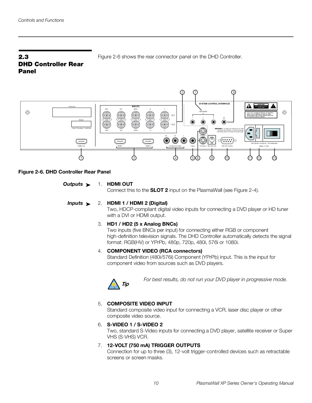
Figure 2-6. DHD Controller Rear Panel
Outputs ➤ 1. HDMI OUT
Connect this to the SLOT 2 input on the PlasmaWall (see Figure
Inputs ➤ 2. HDMI 1 / HDMI 2 (Digital)
Two,
3.HD1 / HD2 (5 x Analog BNCs)
Two inputs (five BNCs per input) for connecting either RGB or component
4.COMPONENT VIDEO (RCA connectors)
Standard Definition (480i/576i) Component (YPrPb) input. This is the input for component video from sources such as DVD players.
For best results, do not run your DVD player in progressive mode.
Tip
5.COMPOSITE VIDEO INPUT
Standard composite video input for connecting a VCR, laser disc player or other composite video source.
6.S-VIDEO 1 / S-VIDEO 2
Two, standard
7.12-VOLT (750 mA) TRIGGER OUTPUTS
Connection for up to three (3),
10 | PlasmaWall XP Series Owner’s Operating Manual |