Installation
3.4
Connections to the PlasmaWall and DHD Controller
Connecting the ➤
PlasmaWall to the DHD Controller
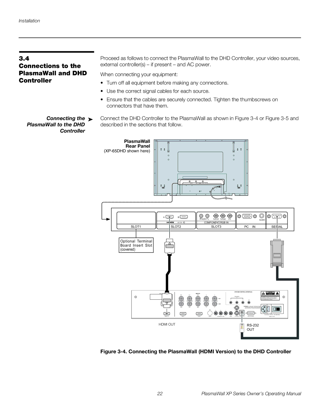
Proceed as follows to connect the PlasmaWall to the DHD Controller, your video sources, external controller(s) – if present – and AC power.
When connecting your equipment:
•Turn off all equipment before making any connections.
•Use the correct signal cables for each source.
•Ensure that the cables are securely connected. Tighten the thumbscrews on connectors that have them.
Connect the DHD Controller to the PlasmaWall as shown in Figure
PlasmaWall
Rear Panel
(XP-65DHD shown here)
A | B | R AUDIO L | PR/CR/R PB/CB/B | Y/G |
|
|
|
|
| AUDIO | |||
|
| COMPONENT/RGB IN |
| |||
| AV IN |
|
| |||
SLOT1 | SLOT2 |
| SLOT3 | PC | IN | SERIAL |
Optional Terminal Board Insert Slot (covered)
Serial No
Model
Video Processor / Controller
HDMI Out
|
|
|
| SYSTEM CONTROL INTERFACE | CAUTION | ! |
|
| INPUTS |
|
| RISK OF ELECTRIC SHOCK | |
|
|
|
| DO NOT OPEN | ||
R/Pr | G/Y | B/Pb | H | V | AVIS: RISQUE DE CHOC | |
TRIGGERS
|
|
|
|
|
|
|
|
| CAUTION: TO REDUCE THE RISK OF ELECTRIC |
|
|
|
|
| HD1 |
|
|
| SHOCK, DO NOT REMOVE COVER. NO USER- |
|
|
|
|
|
|
|
| SERVICEABLE PARTS INSIDE. REFER SERVICING | |
|
|
|
|
|
| 1 | 2 | 3 | TO QUALIFIED SERVICE CENTER. |
|
|
|
|
|
| IR | |||
|
|
|
|
| HD2 |
|
|
|
|
|
|
|
|
|
|
|
|
| WARNING: TO REDUCE THE RISK OF FIRE |
R/Pr | G/Y | B/Pb | H | V |
|
|
|
| OR ELECTRIC SHOCK, DO NOT EXPOSE |
|
|
|
|
|
|
|
|
| THIS APPLIANCE TO RAIN OR MOISTURE. |
|
|
|
| SDI | Pr | Y |
|
| |
|
|
|
| Pb |
|
|
HDMI 1 | HDMI 2 | Option | Component Video | Video | Made In USA |
HDMI OUT
OUT
Figure 3-4. Connecting the PlasmaWall (HDMI Version) to the DHD Controller
22 | PlasmaWall XP Series Owner’s Operating Manual |