Controls and Functions
1.SLOT 1 Not used.
2.SLOT 2 (DVI-D or Dual HDMI input)
Controller to this input.
If SLOT 2 is equipped with an Dual HDMI input board, connect the HDMI output from the DHD Controller to input “A” on this board.
If SLOT 2 is equipped with a
3.SLOT 3 Not used.
4.PC IN Not used.
5.RS-232C (9-pin, male D-Sub)
Connect the
6.POWER INPUT
Connect the PlasmaWall to AC power here.
2.2
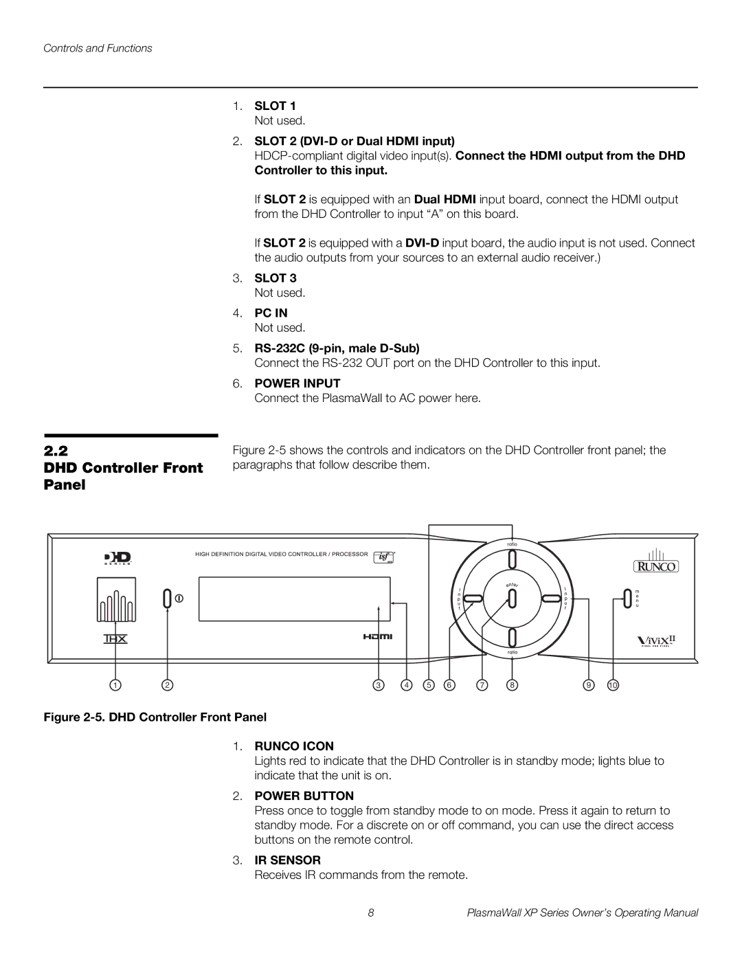
DHD Controller Front Panel
1 | 2 | 3 | 4 | 5 | 6 | 7 | 8 | 9 | 10 |
Figure 2-5. DHD Controller Front Panel
1.RUNCO ICON
Lights red to indicate that the DHD Controller is in standby mode; lights blue to indicate that the unit is on.
2.POWER BUTTON
Press once to toggle from standby mode to on mode. Press it again to return to standby mode. For a discrete on or off command, you can use the direct access buttons on the remote control.
3.IR SENSOR
Receives IR commands from the remote.
8 | PlasmaWall XP Series Owner’s Operating Manual |
