initialization
TO REGISTER/DELETE THE MASTER ID (CARD)
The product will switch to Registration mode when presented with the master card in Reader mode.
The product will switch to Reader mode when presented with the master card in Registration mode.
1.If you want to register a new master card, initialize the system before proceeding. Refer to “Initializing the system using the DIP switch”. (on page 20)
2.When the initialization is completed, the product outputs a voice message with the green and orange indicators turned on, then present the master card.
3.When you present the card to the product (beep once when it is read), it will beep three times with a voice message output.
4.The blinking green and orange indicators indicate that the product switches to Master mode.
•Then, register normal users if you want to.
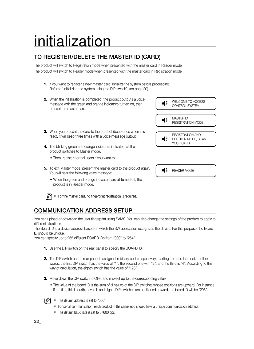
Q | WELCOME TO ACCESS |
| CONTROL SYSTEM |
Q | MASTER ID |
| REGISTRATION MODE |
Q | REGISTRATION AND |
DELETION MODE, SCAN | |
| YOUR CARD |
5. To exit Master mode, present the master card to the product again. | Q READER MODE |
You will hear the following voice message: |
|
• When the green and orange indicators are all turned off, the |
|
product is in Reader mode. |
|
M For the master card, no fingerprint registration is required.
COMMUNICATION ADDRESS SETUP
You can upload or download the user fingerprint using SAMS. You can also change the settings of the product to apply to different situations.
The Board ID is a device address based on which the SW application recognizes the device. For this purpose, the Board ID should be unique.
You can specify up to 255 different BOARD IDs from “000” to “254”.
1.Use the DIP switch on the rear panel to specify the BOARD ID.
2.The DIP switch on the rear panel is assigned in binary code respectively, starting from the leftmost. In other words, the first DIP switch has the value of “1”, the second one with “2”, and the third is “4”. According to this way of calculation, the eighth switch has the value of “128”.
3.Move down the DIP switch to OFF, and move it up to the corresponding value.
•The value of the board ID is the sum of all values of the DIP switches whose positions are upward. For instance, if the first, third, fourth, seventh and eighth DIP switches are positioned upward, the board ID will be “205”.
M The default address is set to “000”.
For serial communication, each product in the same loop should have a unique communication address.
The default baud rate is set to 57600 bps.
22_ initialization