installation and external connection
Input Connection
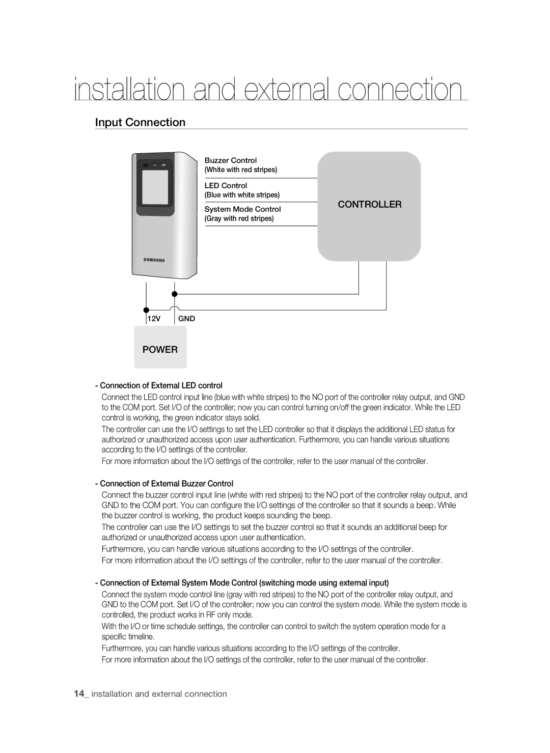
Buzzer Control (White with red stripes)
LED Control
(Blue with white stripes)
System Mode Control | CONTROLLER |
| |
(Gray with red stripes) |
|
|
|
12V
GND
POWER
- Connection of External LED control
Connect the LED control input line (blue with white stripes) to the NO port of the controller relay output, and GND to the COM port. Set I/O of the controller; now you can control turning on/off the green indicator. While the LED control is working, the green indicator stays solid.
The controller can use the I/O settings to set the LED controller so that it displays the additional LED status for authorized or unauthorized access upon user authentication. Furthermore, you can handle various situations according to the I/O settings of the controller.
For more information about the I/O settings of the controller, refer to the user manual of the controller.
- Connection of External Buzzer Control
Connect the buzzer control input line (white with red stripes) to the NO port of the controller relay output, and GND to the COM port. You can configure the I/O settings of the controller so that it sounds a beep. While the buzzer control is working, the product keeps sounding the beep.
The controller can use the I/O settings to set the buzzer control so that it sounds an additional beep for authorized or unauthorized access upon user authentication.
Furthermore, you can handle various situations according to the I/O settings of the controller.
For more information about the I/O settings of the controller, refer to the user manual of the controller.
- Connection of External System Mode Control (switching mode using external input)
Connect the system mode control line (gray with red stripes) to the NO port of the controller relay output, and GND to the COM port. Set I/O of the controller; now you can control the system mode. While the system mode is controlled, the product works in RF only mode.
With the I/O or time schedule settings, the controller can control to switch the system operation mode for a specific timeline.
Furthermore, you can handle various situations according to the I/O settings of the controller.
For more information about the I/O settings of the controller, refer to the user manual of the controller.
14_ installation and external connection