Before wiring and installation
Seals (A)
■ Transport Lock Screws
The mechanism in the changer is “locked” into place during shipment by the transport screws. Be sure to remove the screws prior to installation.
Note:
After removing the transport lock screws, place the supplied seals (A) over the screw holes. Also, place the seals (A) over the holes which are not used for installation. These seals are used to keep dust, which could cause a malfunction, out of the unit.
■Installation and Wiring Precautions
1 To prevent a
¡Be sure to turn off the ignition and remove the negative
Note:
If the changer is to be installed in a car that is equipped with an
2 Do not install the unit in the following locations.
¡Locations exposed to direct sunlight.
¡ Where hot air is discharged from the car heater. ¡ When proper installation is not possible and
where a great deal of vibration is generated.
3 ¡ Be sure to use the supplied brackets and screws.
¡When installing the unit, do not use any screws that are part of the brake or steering system.
4 This unit cannot be installed in any way except that which is authorized (on its side, on its end, at a 45° angle or suspended). Installing it with its side facing down or upside down can cause malfunctioning.
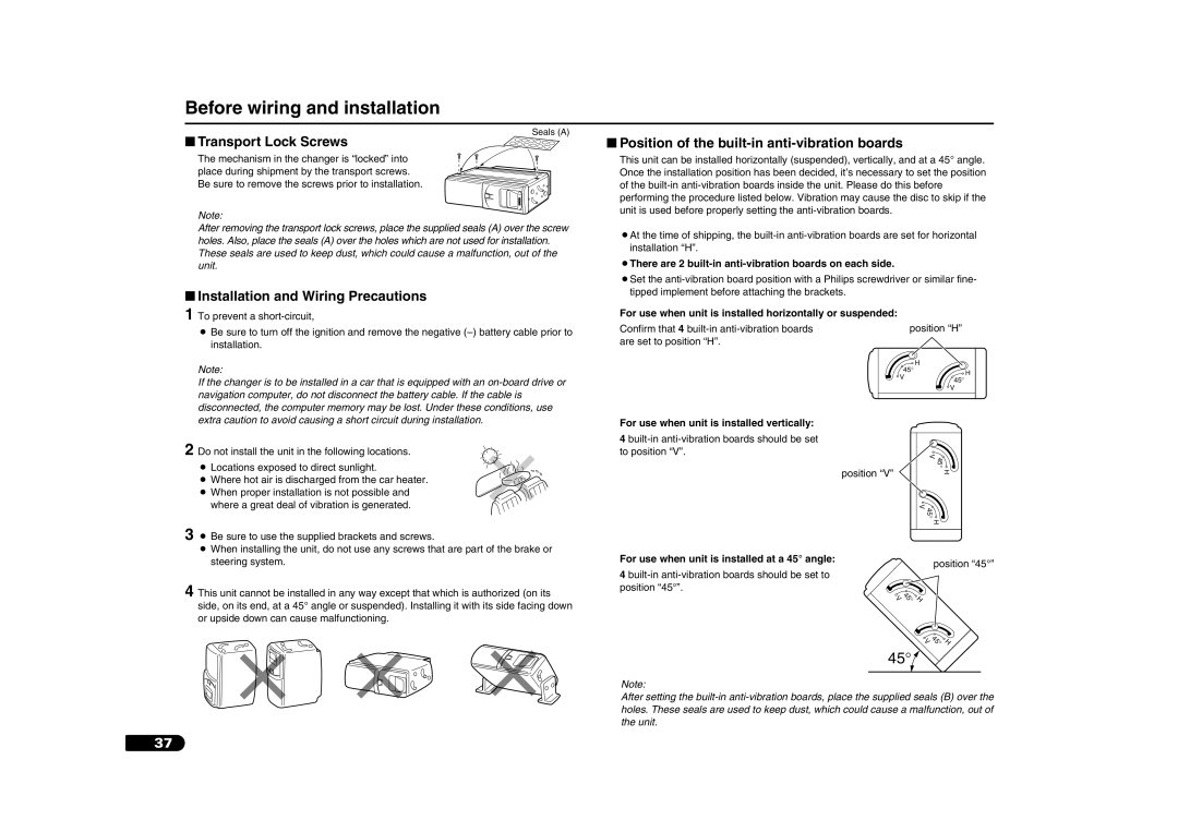
■Position of the built-in anti-vibration boards
This unit can be installed horizontally (suspended), vertically, and at a 45° angle. Once the installation position has been decided, it’s necessary to set the position of the
¡At the time of shipping, the
¡There are 2 built-in anti-vibration boards on each side.
¡Set the
For use when unit is installed horizontally or suspended:
Confirm that 4 |
| position “H” |
|
are set to position “H”. |
|
|
|
|
| H |
|
| 45° | H | |
| V | 45° | |
|
| ||
|
|
| |
|
| V |
|
For use when unit is installed vertically:
4 |
|
|
|
to position “V”. |
| V | 45 |
|
| ||
| position “V” |
| ° |
|
| H | |
| 45 V |
| |
| ° |
| |
|
| H | |
For use when unit is installed at a 45° angle: |
| position “45°” | |
4 |
| ||
|
|
| |
position “45°”. | V 45 |
|
|
|
|
| |
| °H |
|
|
| V | 45 | |
|
| °H | |
45°![]()
Note:
After setting the
37