Altivar
Variable-torque applications
Table of contents
Migration from ATV 38V ATV
Altivar 38 hardware identification
Choosing the Altivar 61 catalog number
ATV38 catalog Power Number
Your catalog number starts with ATV38H
Your catalog number starts with ATV38ED
Selecting the power circuit options
Removable power terminal kit VW3A5881x
Mounting accessories
Air exchanger kit VW3A5880x
Nema type 1 mounting kit
Control circuit options
Separate control card power supply kit VW3A5860x
Control card fan kit VW3A5882x
Remote display terminal VW3A58103
ATV38 and I/O option cards VW3A58201, VW3A58202
Selecting I/O extension cards VW3A58201, VW3A58202
ATV38
PTC
Becomes ATV
PI feedback or summed reference Three different options
VW3A58202
VW3... card
Communication via Modbus network
Selecting communication channels
Communication with Profibus bus VW3A58307
Communication with DeviceNet bus VW3A58309
Communication with Interbus bus VW3A58304E
Communication with Metasys N2 bus VW3A58354U
Communication via Ethernet network VW3A58310
Communication via Fipio bus VW3A58311
Using catalog numbers starting with ATV38H
Installation
ATV 61H075N4
Comparison of dimensions Width Height Depth
ATV 61HU15N4
ATV 61HU22N4
ATV 61HD55N4
ATV 61HD45N4
ATV 61HD75N4
ATV 61HD90N4
Dimensions
Comparison of dimensions
ATV38Hppp product on heatsink
ATV 61H
D22N4
D15N4, D18N4
D30N4, D37N4
D45N4, D55N4, D75N4
ATV61H
ATV 38Hppp 75 kW and y 315 kW Product on heatsink
Drive Filter Width Height Depth Mounting
Mounting the RFI filter
Width Height Depth Mounting
Drive
Comparison of dimensions
RFI filters
VW3
Side mounting against the ATV
Mounting under the drive
Kit catalog
Nema mounting kits
ATV38Hppppp
Kit catalog Product
Kit for UL Nema Type 1 conformity or IP 21 protection
Remote display terminal
Separate control card power supply
Disconnecting the RFI filter if using an IT system
Power cables
Layout of the ATV38 power terminals
Connecting to the Altivar
AWG
Characteristics of the ATV38 power terminals
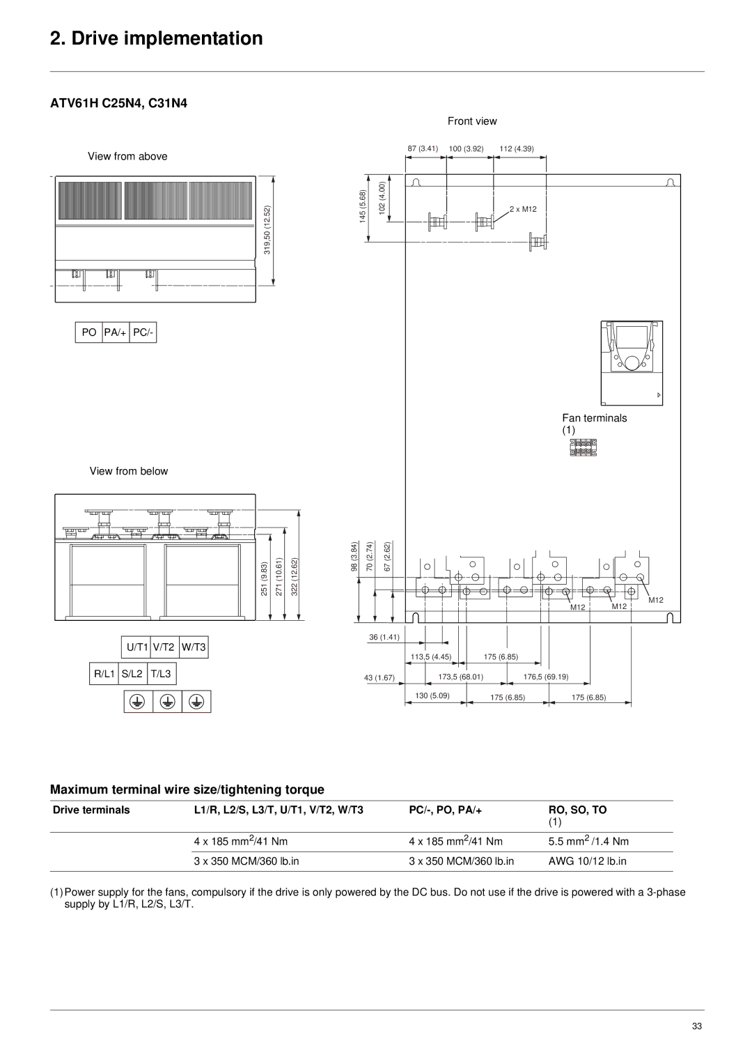
Drive terminals L1/R, L2/S, L3/T, U/T1, V/T2, W/T3
Maximum terminal wire size/tightening torque
PC/-, PO, PA/+
PA, PB
PA, PB RO, SO, to
ATV61H D90M3X, C13N4
ATV61HC16N4
ATV61HC22N4
ATV61H C25N4, C31N4
Control wiring and I/O characteristics
Control and option card logic input wiring
ATV38 value kOhms
LI6 wired as PTC probe
Encoder
General
Installing the communication option card
Acceptance
Check that the drive is turned off
Value Description of parameter values
Option card fault
Schematic diagram
Mixed schematic
Communication via Modbus network
Calculating the polarization resistors
Configuring the address
Configuring the drive
Configuring the drive control mode
Reminder of the various connection methods
PLC configuration and application
Configuring communication monitoring
Reminder of possible connection methods
Address ATV38 switches ATV61 switches 12345678
PLC configuration and application
Configuring polarity on the drive RS 485 bus
Communication via CANopen network
Matching the line termination resistor
Address and Baud rate
Configuring the drive
Communication via Profibus DP network
Configuring the drive address on the Profibus DP network
Address
1234
Communication fault
Configuring the drive in ATV38 Interchangeability mode
Configuring the drive address on the Fipio network
Connecting to the Fipio bus
Communication via Fipio network VW3 A3 311 option card
Presentation
Managing loss of Fipio communication
Altivar 38 PKW indexed periodic variables
Family
Base module
Communication via Interbus network
Configuring the communication parameters
Configuring the drive address on the Modbus Plus network
Communication via Modbus Plus network
ATV38 ATV61
Communication fault
Configuring the drive address on the DeviceNet network
Configuring the drive on the network
Communication via DeviceNet network
MAC
PLC configuration and application
Drive implementation on the DeviceNet network
Implementation of the communication option cards
Implementation of the communication option cards
Implementation of the communication option cards
Implementation of the communication option cards
P06 P06
Communication fault
Using the Bootp protocol
Drive configuration in Expert mode
Communication via Ethernet network
Transmission speed
Faulty Device Replacement FDR
Using the DHCP-FDR protocol
Activating the service
Procedure on the Altivar
Programming the Altivar 38 Ethernet parameters
Modbus service
Available address fields
Xxxx
Ethernet card access to the Modbus server
IO Scanning service
Configuring the periodic parameter assignment table
Modbus functions available
FDR service fault EPF2
Configuring the IO Scanner page from the Http server
Implementation of the communication option cards
Altivar 38 PKW parameter-setting service
Configuring the IO Scanner page using TCP/Modbus messaging
Snmp agent
Description ATV61 register
Communication fault
PDA Altivar page Last Fault = ILF Fault
FDR service fault EPF2
Standard Http server
AS-i
Assignment of the Inputs/Outputs
11 . +/- speed mode
Speed mode, 1 direction of operation
Assignment of inputs/outputs
Speed mode, 2 directions of operation
Configuring the drive logic I/O
Managing the terminal outputs AS-i monitoring bits
Limitations
Pump card
Application-specific option cards
Multi-motor card
Multi-parameter card
Atv61migrationenv1 2006-04