3. Implementation of the communication option cards
Configuring the "IO Scanner" page using TCP/Modbus messaging
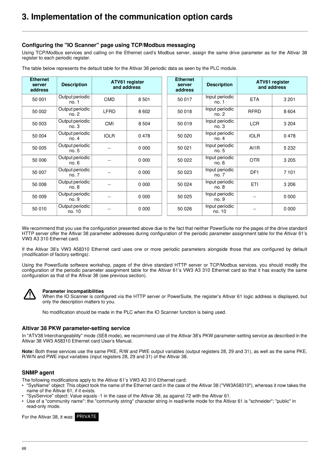
Using TCP/Modbus services and calling on the Ethernet card’s Modbus server, assign the same drive parameter as for the Altivar 38 register to each periodic register.
The table below represents the default table for the Altivar 38 periodic data as seen by the PLC module.
Ethernet | Description | ATV61 register | ||
server | ||||
and address | ||||
address |
| |||
|
|
| ||
50 001 | Output periodic | CMD | 8 501 | |
no. 1 | ||||
|
|
| ||
|
|
|
| |
50 002 | Output periodic | LFRD | 8 602 | |
no. 2 | ||||
|
|
| ||
50 003 | Output periodic | CMI | 8 504 | |
no. 3 | ||||
|
|
| ||
50 004 | Output periodic | IOLR | 0 478 | |
no. 4 | ||||
|
|
| ||
|
|
|
| |
50 005 | Output periodic | 0 000 | ||
no. 5 | ||||
|
|
| ||
50 006 | Output periodic | 0 000 | ||
no. 6 | ||||
|
|
| ||
50 007 | Output periodic | 0 000 | ||
no. 7 | ||||
|
|
| ||
|
|
|
| |
50 008 | Output periodic | 0 000 | ||
no. 8 | ||||
|
|
| ||
50 009 | Output periodic | 0 000 | ||
no. 9 | ||||
|
|
| ||
50 010 | Output periodic | 0 000 | ||
no. 10 | ||||
|
|
| ||
|
|
|
| |
Ethernet | Description | ATV61 register | ||
server | ||||
and address | ||||
address |
| |||
|
|
| ||
50 017 | Input periodic | ETA | 3 201 | |
no. 1 | ||||
|
|
| ||
|
|
|
| |
50 018 | Input periodic | RFRD | 8 604 | |
no. 2 | ||||
|
|
| ||
50 019 | Input periodic | LCR | 3 204 | |
no. 3 | ||||
|
|
| ||
50 020 | Input periodic | IOLR | 0 478 | |
no. 4 | ||||
|
|
| ||
|
|
|
| |
50 021 | Input periodic | AI1R | 5 232 | |
no. 5 | ||||
|
|
| ||
50 022 | Input periodic | OTR | 3 205 | |
no. 6 | ||||
|
|
| ||
50 023 | Input periodic | DF1 | 7 101 | |
no. 7 | ||||
|
|
| ||
|
|
|
| |
50 024 | Input periodic | ETI | 3 206 | |
no. 8 | ||||
|
|
| ||
50 025 | Input periodic | 0 000 | ||
no. 9 | ||||
|
|
| ||
50 026 | Input periodic | 0 000 | ||
no. 10 | ||||
|
|
| ||
|
|
|
| |
We recommend that you use the configuration presented above due to the fact that neither PowerSuite nor the pages of the drive standard HTTP server offer the Altivar 38 parameter addresses during configuration of the periodic parameter assignment table for the Altivar 61’s VW3 A3 310 Ethernet card.
If the Altivar 38’s VW3 A58310 Ethernet card uses one or more periodic parameters alongside those that are configured by default (modification of factory settings):
Using the PowerSuite software workshop, pages of the drive standard HTTP server or TCP/Modbus services, you should modify the configuration of the periodic parameter assignment table for the Altivar 61’s VW3 A3 310 Ethernet card so that it has exactly the same configuration as that of the Altivar 38 (see previous section).
Parameter incompatibilities
When the IO Scanner is configured via the HTTP server or PowerSuite, the register’s Altivar 61 logic address is displayed, but only the description matters to you.
No modification should be made in the PLC when the IO Scanner function is being used.
Altivar 38 PKW parameter-setting service
In "ATV38 Interchangeability" mode (SE8 mode), we recommend use of the Altivar 38’s PKW
Note: Both these services use the same PKE, R/W and PWE output variables (output registers 28, 29 and 31), as well as the same PKE, R/W/N and PWE input variables (input registers 28, 29 and 31) of the Altivar 38.
SNMP agent
The following modifications apply to the Altivar 61’s VW3 A3 310 Ethernet card:
•"SysName" object: This object took the name of the Ethernet card in the case of the Altivar 38 ("VW3A58310"), whereas it now takes the name of the Altivar 61, if it exists.
•"SysService" object: Value equals
•Use of a "community name": the "community string" character string in read/write mode for the Altivar 61 is "schneider"; "public" in
For the Altivar 38, it was: PRIVATE
68