INSTALLATION
3. INSTALLATION
3.1General
The following parts are supplied with a standard HS50 system:
−Sensor unit with 1 meter cable w/connector and 4 fastening bolts
−Display unit with 15 meters cable to the Processing unit and flush mounting kit
−Processing unit including 4 fastening screws
−30 meters cable to be used between Sensor unit and Processing unit
−Documentation
Caution!
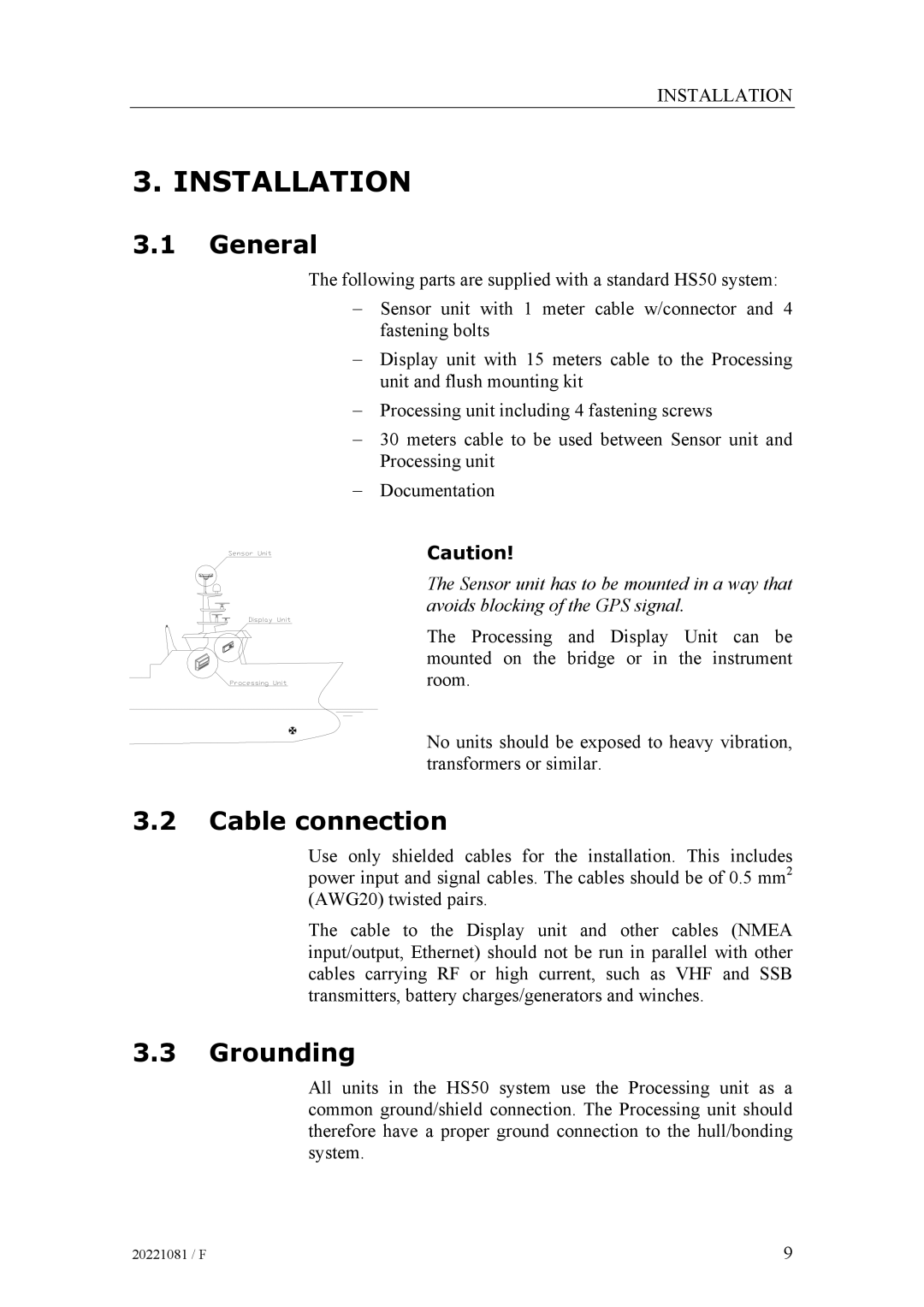
The Sensor unit has to be mounted in a way that avoids blocking of the GPS signal.
The Processing and Display Unit can be mounted on the bridge or in the instrument room.
No units should be exposed to heavy vibration, transformers or similar.
3.2Cable connection
Use only shielded cables for the installation. This includes power input and signal cables. The cables should be of 0.5 mm2 (AWG20) twisted pairs.
The cable to the Display unit and other cables (NMEA input/output, Ethernet) should not be run in parallel with other cables carrying RF or high current, such as VHF and SSB transmitters, battery charges/generators and winches.
3.3Grounding
All units in the HS50 system use the Processing unit as a common ground/shield connection. The Processing unit should therefore have a proper ground connection to the hull/bonding system.
20221081 / F | 9 |