INSTALLATION
Mechanical installation
The Sensor unit may be mounted in the mast or directly on the deck.
The dimensional drawing for the Sensor unit on page 50 shows dimensions and internal distance for the mounting holes and the cable outlet.
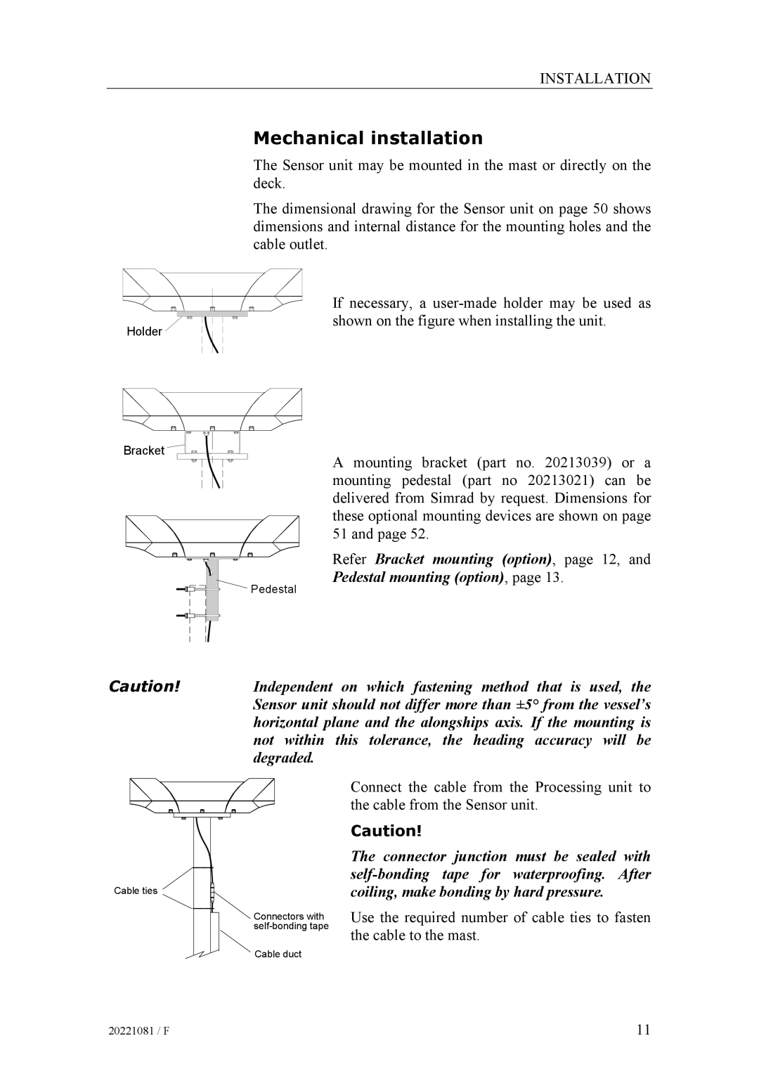
Holder
If necessary, a
Bracket
A mounting bracket (part no. 20213039) or a mounting pedestal (part no 20213021) can be delivered from Simrad by request. Dimensions for these optional mounting devices are shown on page 51 and page 52.
Refer Bracket mounting (option), page 12, and
Pedestal mounting (option), page 13.
Pedestal
Caution!
Independent on which fastening method that is used, the Sensor unit should not differ more than ±5° from the vessel’s horizontal plane and the alongships axis. If the mounting is not within this tolerance, the heading accuracy will be degraded.
Cable ties
Connectors with
Cable duct
Connect the cable from the Processing unit to the cable from the Sensor unit.
Caution!
The connector junction must be sealed with
Use the required number of cable ties to fasten the cable to the mast.
20221081 / F | 11 |