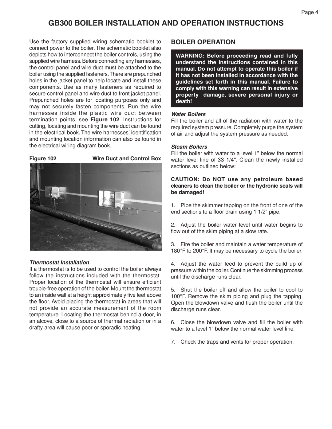
GB300 specifications
The Smith Cast Iron Boilers GB300 series is renowned for its robust construction and exceptional performance, making it a preferred choice for commercial and industrial applications. This line of boilers is designed to provide reliable and efficient heating solutions for a variety of facilities, including schools, hospitals, and manufacturing plants.One of the standout features of the GB300 series is its durable cast iron construction. Built to withstand the demands of heavy-duty operation, the cast iron material ensures longevity and resilience against thermal cycling stresses. This design not only enhances the boiler's lifespan but also ensures that it maintains optimal performance over time, even in rigorous conditions.
The GB300 series is equipped with advanced technologies that contribute to its efficiency and ease of use. For instance, the boilers incorporate a flexible firing system that allows for a range of firing rates. This adaptability ensures that the boiler can efficiently meet varying heating loads. Additionally, the use of a multi-pass heat exchanger design maximizes heat transfer, significantly improving overall efficiency and reducing fuel consumption.
Another key characteristic of the GB300 boilers is the user-friendly control system. The integrated control panel provides operators with real-time monitoring and management capabilities, allowing for precise adjustment of temperature and pressure settings. This feature not only enhances operational efficiency but also aids in maintaining safety standards.
The GB300 series also emphasizes safety, featuring multiple levels of protection, including low water cut-off, high-pressure switches, and safety valves. These safety mechanisms ensure reliable operation and minimize the risk of operational hazards, providing peace of mind for operators and facility managers.
Versatility is another remarkable attribute of the Smith Cast Iron Boilers GB300 series. These boilers can be used in various configurations, whether as a standalone unit or as part of a more extensive heating system. This flexibility makes the GB300 series suitable for diverse applications and facility sizes.
In summary, the Smith Cast Iron Boilers GB300 series is a powerful heating solution that combines durability, efficiency, and advanced technology. Its robust cast iron construction, flexible firing capabilities, and comprehensive safety features make it an ideal choice for those seeking reliable heating systems in demanding environments. The GB300 series stands out as a testament to Smith's commitment to quality and innovation in the boiler industry.

