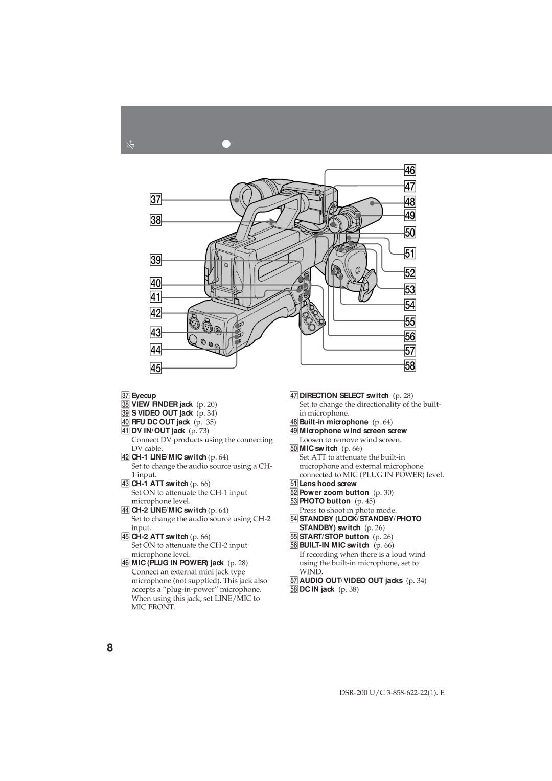
Identifying the parts
| $¤ | |
| $¦ | |
#¦ | $¥ | |
#¥ | $» | |
%¼ | ||
| ||
#» | %Á | |
| ||
$¼ | %ª | |
%£ | ||
$Á | ||
%¢ | ||
$ª | ||
%° | ||
$£ | ||
%¤ | ||
| ||
$¢ | %¦ | |
$° | %¥ |
#¦ Eyecup
#¥ VIEW FINDER jack (p. 20) #» S VIDEO OUT jack (p. 34) $¼ RFU DC OUT jack (p. 35) $Á DV IN/OUT jack (p. 73)
Connect DV products using the connecting DV cable.
$ª
Set to change the audio source using a CH- 1 input.
$£
Set ON to attenuate the
$¢
Set to change the audio source using
$°
Set ON to attenuate the
$¤ MIC (PLUG IN POWER) jack (p. 28) Connect an external mini jack type microphone (not supplied). This jack also accepts a
MIC FRONT.
$¦DIRECTION SELECT switch (p. 28)
Set to change the directionality of the built- in microphone.
$»Microphone wind screen screw Loosen to remove wind screen.
%¼MIC switch (p. 66)
Set ATT to attenuate the
%ÁLens hood screw
%ªPower zoom button (p. 30) %£PHOTO button (p. 45)
Press to shoot in photo mode.
%¢STANDBY (LOCK/STANDBY/PHOTO STANDBY) switch (p. 26)
%°START/STOP button (p. 26)
If recording when there is a loud wind using the
%¦AUDIO OUT/VIDEO OUT jacks (p. 34) %¥DC IN jack (p. 38)
8
