Flat Panel Color Television
Safety
Installing
Notification
Owner’s Record
Table of Contents
Inserting Batteries into the Remote Control
Unpacking
Preventing the TV from Falling Down
Attach the supplied bracket with the screw
Connector Types
Supplied 75-ohm coaxial cable
Video cable
AUDIO/VIDEO cable
TV front panel
Identifying Front and Rear Connectors
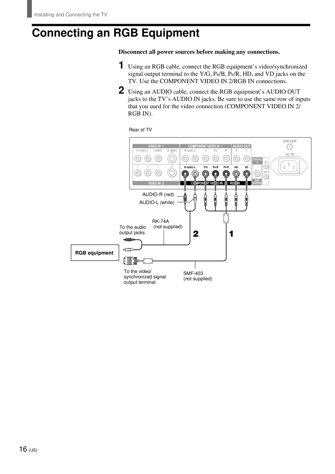
Rear of TV
Basic Connections Connecting Cable TV or Antenna
Connecting directly to cable or an antenna
Cable box connections
VHF only or VHF/UHF or cable
Connecting a VCR and Cable
Disconnect all power sources before making any connections
When connecting both Video OUT and S Video OUT
Tip
Connecting a Satellite Receiver
Video
Connecting a Satellite Receiver with a VCR
Rear of TV Antenna Satellite receiver cable
Connecting an Audio Receiver
When using your audio system speakers
Connecting a DVD Player with Component Video Connectors
Connecting a DVD Player with A/V Connectors
Connecting a Digital TV Receiver
Connecting a Sub Woofer
Connecting an RGB Equipment
To cancel Auto Program
Setting the Channels
To perform Auto Program again
To watch Catv channels
To skip channels
Press V/v to select the channel you want to skip Then press
Press V/v to select Skip, then press
Menu
Selecting the On-screen Menu Language
Press
Power
Watching the TV
VOL
Other button operations
Watching with closed caption
Select
When watching TV
When watching movies on videotapes or
Enjoying High-quality Pictures and Sounds
DVD
Selecting the Picture Mode
Picture Mode
Selecting the Effect Mode
Press V/v to select Adjust Sound, then press
Press V/v to select Picture/Sound Control Then press
Press V/v to select Effect, then press
Power Saving
Saving the Power Consumption
To cancel the Power Saving mode
Using the Wide Screen Mode
Changing the Wide Screen Mode automatically
Changing the Wide Screen Mode manually
Changing the Wide Setup
Wide Mode
Auto Wide Mode1
How Wide Screen Mode works in Auto Wide Mode1 and Mode2
Changing the Auto Wide setting
Wide Screen Mode
Original picture Auto Wide Mode1 Auto Wide Mode2
Setting the Video Inputs
Video
RGB
To watch the TV
Operating Video Equipment with Your TV Remote Control
Programming the remote control
Sony equipment Programmable code number
VHS VCR
Manufacturer’s codes
VCRs
DVD Players
Cable Boxes
Operating optional equipment
Operating a DVD player
Operating a cable box
Operating a VCR
Using Favorite Channels
Setting your favorite channels
Press V/v to select Favorite Channel, then
Press V/v to select the desired channel, then
Press Favorites Favorite Channel options appear
Watching Favorite Channel
Favorites TV/SAT
To adjust screen size
Adjusting the Picture Size/Position
To adjust screen position
Using the Picture Control Mode Option
Press V/v/B/b to adjust each option, then press
To adjust the Screen Size
To adjust the Screen Shift
Press V/v/B/b to make the desired adjustment Then press
Adjustable options
Option Press v/B Press V/b
Con t r a s t
Using the Sound Control Option
To reset to the factory settings
Select Reset in , then press
Option Description Setting
Picture
Using the Parental Control Feature
Selecting Stereo or Bilingual Programs
You can enjoy stereo, bilingual and mono programs
MTS/SAP Guide
Enter a four digit password using the 0-9 buttons
Activating the Parental Control feature
Make sure that Parental Control is selected Then press
To deactivate the Parental Control feature
To change the password
Press V/v to select Lock, then press
Viewing blocked programs
Selecting a Custom Rating
Make sure that Movie Rating is selected, then Press
Press B to return to the Custom menu
To select a rating in Canada, go to step
To block TV programs and/or movies for
Which a rating is not given NR and N/A
What the Ratings Mean
Ratings in the U.S.A
Sony’s predetermined ratings
Movie ratings
Ratings in Canada
About the extenders of U.S. TV ratings
Canadian English Language ratings
Canadian French Language ratings
Adjusting Advanced AV Setting Options
To adjust the setting
Menu category Menu item Setting option
To select the option
Menu category Menu item Setting option
50 US
To cancel the Sleep timer
Turning Off the TV Automatically
Sleep
Press Sleep repeatedly until Sleep Off appears
Setting the Current Time
Press V/v to select Timer/Clock, then press
Press B three times
Press V/v to select Clock Display, then press
Controlling Power On/ Off Automatically
Setting the daylight saving
Daylight-saving setting Description
Press V/v to select On or Off, then press
Press V/v to select Timer Mode, then press
To cancel On/Off Timer
Press V/v to select Off, On, or On/Off Then press
To turn the TV on and off at a specified time everyday
Troubleshooting
Self-diagnosis function
Case1
Case
No picture
Trouble symptoms and remedies
Poor picture
Wide Screen Mode changes
Remote control does not
No sound./Noisy sound
Cannot operate the menu
Specifications
Index
MTS
Catv
Avis
Table des matiè res
Insertion des piles dans la té lé commande
Dé ballage
Pré vention des chutes du té lé viseur
Immobilisez le crochet fourni avec la vis
Types de connecteurs
Câ ble coaxial 75 ohms fourni
Câ ble S-VIDEO
Câ ble AUDIO/VIDEO
Panneau avant du té lé viseur
Identification des connecteurs avant et arriè re
Arriè re du té lé viseur
Raccordements de base Raccordement au câ ble ou à l’antenne
Raccordement direct au câ ble ou à l’antenne
Raccordements du dé codeur
VHF uniquement ou VHF/UHF ou câ ble
Lorsque vous raccordez les prises Video OUT et S Video OUT
Raccordement d’un magné toscope et du câ ble
Conseil
Raccordement d’un ré cepteur satellite
Raccordement d’un ré cepteur satellite avec un magné toscope
Raccordement d’un ré cepteur audio
12 FR
Raccordement d’un lecteur DVD avec des connecteurs A/V
Raccordement d’un ré cepteur de té lé vision numé rique
Raccordement d’un caisson de graves
Raccordement d’un appareil RVB
Appareil RVB
Ré glage des canaux
Pour ignorer des canaux
Pour regarder des canaux de câ blodistribution
Appuyez sur V/v pour sélectionner Saut, puis
Appuyez sur V/v pour sélectionner Langue Puis appuyez sur
Sé lection de la langue des menus à l’é cran
Ang ue
Appuyez sur la touche Power de la télécommande
Réglez le volume à l’aide des touches VOL+
Regarder la té lé vision
Fonctions des autres touches
Utilisation des sous-titres
Sélectionner Pour
Lorsque vous regardez la té lé vision
Pour profiter d’images et de sons de haute qualité
Lorsque vous regardez des films sur cassette ou DVD
Sé lection du Mode image
Clatant
Salon
Film
Sé lection du mode Effet
Mode Image L o n
Appuyez sur V/v pour sélectionner Effet, puis
G u s
Appuyez sur Power Saving
Pour annuler le mode É con. d’é nergie é conomie d’é nergie
Ré duction de la consommation d’é nergie
Simul. simulation
Utilisation du mode grand format
Modification automatique du mode grand format
Large zoom large
Plein
Modification manuelle du mode grand format
Modification du Ré glage grand format
Gr. format auto grand format automatique Mode1
Gr. format auto grand format automatique Mode2
Remarques sur le mode grand format
Ré glage des entré es vidé o
Pour regarder la té lé vision
Appuyez sur les touches 0-9 et Enter ou CH +
Appuyez sur Pour sélectionner Affichage
Té lé commande de votre té lé viseur
Programmation de la té lé commande
Pilotage d’appareils vidé o avec la
Pour programmer un décodeur ou un récepteur satellite
Codes fabricant
Magnétoscopes
Lecteurs DVD
Décodeurs
Pilotage d’appareils en option
Pilotage d’un lecteur DVD
Pilotage d’un dé codeur
Pilotage d’un magné toscope
Utilisation de la fonction Canal pré fé ré
Ré glage de vos canaux pré fé ré s
Regarder votre canal pré fé ré
Ré glage de la taille et de la position de l’image
Pour ajuster la taille de l’écran
Pour ajuster la position de l’écran
G l a g e g r a n d f o r m a t
Options de ré glage des Modes image
Pour ajuster le Centrage de l’écran
Option Appuyez sur v/B Appuyez sur V/b
Options réglables
Con t r a s t e
Utilisation de l’option Ré glages son
Pour revenir aux ré glages par dé faut
Option
Réglage
Aigus +20
Vous pouvez écouter des émissions stéréo, bilingues et mono
Utilisation de la fonction Surveillance parentale
Indication du son Description
Appuyez sur V/v pour sélectionner Pays, puis
Activation de la fonction Surveillance parentale
Conseils
Appuyez sur V/v pour sélectionner Blocage Puis appuyez sur
Visualisation de programmes bloqué s
Pour dé sactiver la fonction Surveillance parentale
Pour modifier le mot de passe
Sé lection d’un classement personnalisé
Appuyez sur B pour revenir au menu habitude
B l i c d u f i l m
A s s i f i c a t i o n G B
Etats-Unis, puis appuyez sur
Classification G-B
Signification des classements
Classements aux É tats-Unis
Classements Sony pré dé finis
Classements des films aux É tats-Unis
Classements au Canada
Classements autorisé s pour le Canada anglais
Classements autorisé s pour le Canada franç ais
Ré glage des options de ré glage AV avancé es
Pour sé lectionner l’option
Pour ajuster le ré glage
Catégorie de menu É lément de menu Option de réglage
Catégorie de menu Lément de menu Option de réglage
Component Video in 2/RGB
Touche Menu réglage par défaut
Mettre le té lé viseur automatiquement hors tension
Pour annuler la minuterie de veille
Réglez l’heure actuelle
Ré glage de l’heure actuelle
Appuyez trois fois sur B
Contrô le automatique de la mise sous/hors tension
Appuyez sur V/v pour sélectionner Marche Puis appuyez sur
Ré glage de l’heure d’é té
Réglage de l’heure d’été Description
Appuyez sur V/v pour sélectionner Mode
Minuterie, puis appuyez sur
Pour annuler la minuterie de mise sous/hors tension
Sélectionnez Arrêt à l’étape
Dé pannage
Fonction d’auto-diagnostic
Cas
Aucune image
Symptô mes et solutions
’image est mauvaise
Le mode grand format change
La télécommande ne
Pas de son/Son parasité
Impossible d’activer le menu
Spé cifications
Econ. d’énergie
Precaución
Notificació N
Ajuste de la configuració n
Índice
Instalació n y conexió n del TV
Para ver televisió n
Desembalaje
Para evitar que el TV se caiga
Inserció n de las pilas en el control remoto
Monte con el tornillo la abrazadera provista
Tipos de conectores
Cable coaxial de 75 ohmios suministrado
Cable S Video
Cable AUDIO/VIDEO
Panel frontal del TV
Identificació n de los conectores frontales y posteriores
Parte posterior del TV
Conexiones del decodificador
Conexió n directa por cable o a una antena
VHF solamente o VHF/UHF o cable
Conexió n de Video OUT y S Video OUT
Conexió n de una videograbadora y cable
Sugerencia
Conexió n de un receptor de saté lite
Conexió n de un receptor de saté lite con una videograbadora
Conexió n de un receptor de audio
Al utilizar los altavoces del sistema de audio
12 ES
Conexió n de un reproductor de DVD con conectores A/V
Conexió n de un receptor de TV digital
Conexió n de un potenciador de graves
Conexió n de un equipo RGB
Programació n de canales
Para volver a realizar la programació n automá tica
Para cancelar Programa auto
Para mirar canales Catv
Para omitir canales
Oprima V/v para seleccionar Omitir, luego
Selecció n del idioma de menú en pantalla
Oprima V/v para seleccionar Ajuste Inicial, luego oprima
Oprima V/v para seleccionar Idioma, luego
I oma G l i s h
Oprima Power en el control remoto
Ajuste el volumen con los botones VOL +
Para ver televisió n
Seleccione el canal deseado con los botones 0-9 y Enter
Vista con subtítulos
Seleccione Para
Cuando mire televisió n
Para disfrutar de una buena calidad de imagen y sonido
Cuando mire películas de video o DVD
Selecció n del modo de imagen
Oprima V/v para seleccionar Ajuste sonido Luego oprima
Selecció n del modo de efecto
Oprima
Ahorro del consumo de energía
Para cancelar el modo de ahorro de energía
Simulac Simulación
Uso del modo de pantalla panorá mica
Para cambiar automá ticamente el modo panorá mico
Zoomanch
Completa
Cambio manual del modo panorá mico
Cambio del ajuste panorá mico
Panorámico auto Modo1
Panorámico auto Modo2
Cambio del ajuste Panorá mico auto
Notas sobre el modo de pantalla panorámica
Modo panorámico
Imagen original Panorámico auto Modo1 Panorámico auto Modo2
Ajuste de las entradas de video
Para mirar la TV
Oprima los botones 0-9 y Enter o CH +
Oprima Para seleccionar Indicación en Pantalla
Programació n del control remoto
Para programar un decodificador o un receptor de satélite
Oprima SAT/CABLE Function
Equipos Sony Nú mero de código programable
Có digos del fabricante
Videograbadoras
Reproductores DVD
Receptores de satélite
Funcionamiento de equipos opcionales
Funcionamiento de un reproductor DVD
Funcionamiento de un decodificador
Para Oprima
Uso de los canales favoritos
Ajuste de los canales favoritos
Oprima V/v para seleccionar Ajuste TV Luego oprima
Oprima V/v para seleccionar Canal favorito Luego oprima
Oprima Favorites Aparece la opció n Canal favorito
Para mirar el canal favorito
Favorites
Para ajustar el tamañ o de la pantalla
Ajuste del tamañ o/ posició n de la imagen
Para ajustar la posición de la pantalla
Oprima V/v/B/b para ajustar cada opció n Luego oprima
Uso de la opció n Modo de control de imagen
Para ajustar el Desplazamiento pantalla
Oprima V/v para seleccionar Ajuste imagen Luego oprima
Opciones que se pueden ajustar
N t r a s t e
Uso de la opció n Control de sonido
Si oprime y mantiene v, aparecen las siguientes opciones
Para restaurar los ajustes de fá brica
Seleccione Restaurar en el paso 5, luego oprima
Oprima V/v/B/b para realizar el ajuste Deseado, luego oprima
Opción Oprima v/B Oprima V/b
Selecció n de programas esté reo o bilingü es
Uso de la opció n Bloqueo seguridad
Puede disfrutar de programas estéreo, bilingü es y mono
Indicación de sonido Descripción
Activació n de la funció n Bloqueo seguridad
Oprima V/v para seleccionar País País Luego oprima
Oprima V/v para seleccionar Bloqueo, luego
Para mirar programas bloqueados
Para desactivar la funció n Bloqueo seguridad
Ajuste Bloqueo en Apagar dentro del menú Bloqueo seguridad
Selecció n de una clasificació n personalizada
Oprima V/v para seleccionar Clasif TV, luego
A s i f f i l m e
A s i f Lme
Clasificasió N EE.UU., luego oprima
Clasificasió N Inglesa
Significado de las clasificaciones
Clasificaciones en EE.UU
Clasificaciones predeterminadas de Sony
Clasificaciones de películas en EE.UU
Clasificaciones en Canadá
Clasificaciones en inglé s canadiense
Clasificaciones en francé s canadiense
Ajuste de las opciones de configuració n avanzadas de AV
Para ajustar la configuració n
Para seleccionar la opció n
Categoría de menú Elemento de menú Opción de ajuste
Ajuste Píxel
NÚ Mero Serie
Para cancelar el temporizador de reposo
Apagado automá tico del
Oprima Menu Oprima B tres veces
Ajuste de la hora actual
Oprima V/v para seleccionar Pantalla reloj Luego oprima
Control automá tico de encendido/apagado
Ajuste del horario de verano
Oprima V/v para seleccionar Encender o Apagar, luego oprima
Oprima Menu para salir de la pantalla del
Para cancelar Tempor act/des
Oprima V/v para seleccionar Modo Tempor
Seleccione Apagar en el paso
Modo tempor Descripción
Solució n de problemas
Funció n de autodiagnó stico
Caso
Caso 2-a Si aparece NG en la columna Temperatura
No hay imagen
Síntomas y soluciones de problemas
Imagen pobre
Sin sonido./Sonido ruidoso
No se puede utilizar el menú
El modo pantalla panorámica
Cambia automáticamente
Especificaciones
Reproductor DVD