2.The following applications require a larger feed stand (optional 3” or 4”) to prevent material bridging:
o Machines with a total throughput over 200 lbs./hr.
o Machines running regrind larger than 5/16” screen size o Processes with a high percentage of regrind (>30%) o
o Consult factory for any special requirements.
3.Optimum mounting of the Digital Dosing feeder is shown in Figure 4, with the additive being dosed in the first few flights of the feed screw.
4.The controller should be remote mounted for operator convenience. The control unit must not be exposed to temperatures above 45° C (115° F), or excessive moisture.
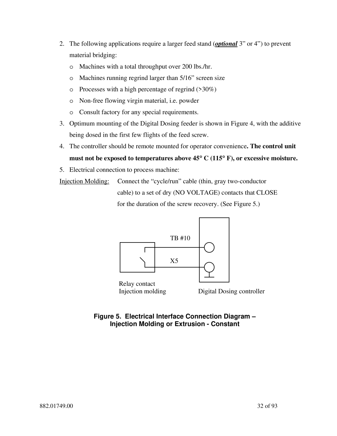
5.Electrical connection to process machine:
Injection Molding: Connect the “cycle/run” cable (thin, gray
| TB #10 |
| X5 |
Relay contact |
|
Injection molding | Digital Dosing controller |
Figure 5. Electrical Interface Connection Diagram –
Injection Molding or Extrusion - Constant
882.01749.00 | 32 of 93 |