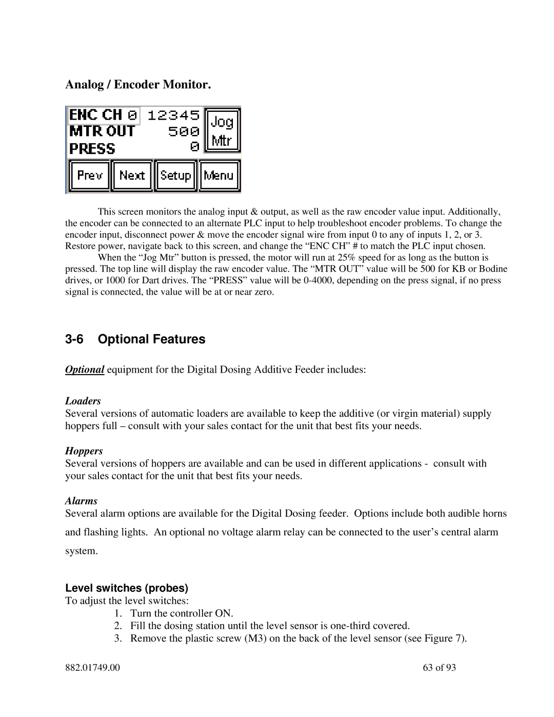
Analog / Encoder Monitor.
This screen monitors the analog input & output, as well as the raw encoder value input. Additionally, the encoder can be connected to an alternate PLC input to help troubleshoot encoder problems. To change the encoder input, disconnect power & move the encoder signal wire from input 0 to any of inputs 1, 2, or 3.
Restore power, navigate back to this screen, and change the “ENC CH” # to match the PLC input chosen. When the “Jog Mtr” button is pressed, the motor will run at 25% speed for as long as the button is
pressed. The top line will display the raw encoder value. The “MTR OUT” value will be 500 for KB or Bodine drives, or 1000 for Dart drives. The “PRESS” value will be
3-6 Optional Features
Optional equipment for the Digital Dosing Additive Feeder includes:
Loaders
Several versions of automatic loaders are available to keep the additive (or virgin material) supply hoppers full – consult with your sales contact for the unit that best fits your needs.
Hoppers
Several versions of hoppers are available and can be used in different applications - consult with your sales contact for the unit that best fits your needs.
Alarms
Several alarm options are available for the Digital Dosing feeder. Options include both audible horns and flashing lights. An optional no voltage alarm relay can be connected to the user’s central alarm system.
Level switches (probes)
To adjust the level switches:
1.Turn the controller ON.
2.Fill the dosing station until the level sensor is
3.Remove the plastic screw (M3) on the back of the level sensor (see Figure 7).
882.01749.00 | 63 of 93 |