Machine-Side Hopper Loaders
4.1. Unpacking
The loader is insensitive to shocks and can be mounted directly onto the processing machine, on a machine hopper, a drying hopper or a dosing and blending unit.
The equipment is delivered as a complete assembly.
Use the following procedure to prepare the machine for assembly:
1.Unpack the equipment.
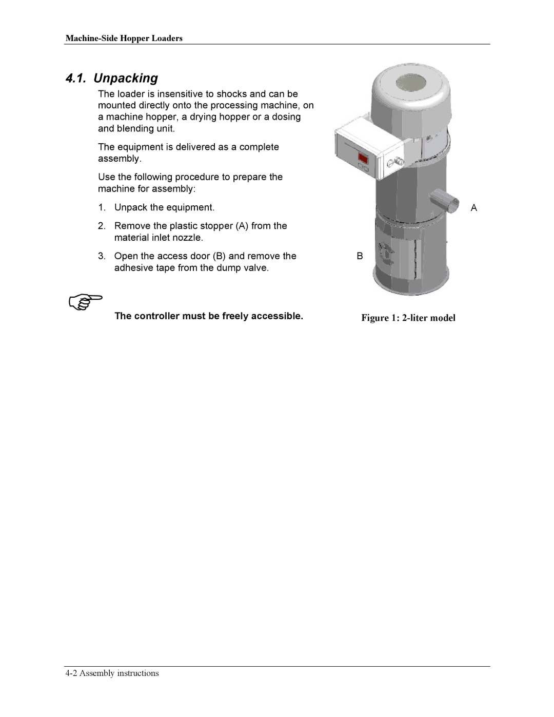
2.Remove the plastic stopper (A) from the material inlet nozzle.
3.Open the access door (B) and remove the adhesive tape from the dump valve.
FThe controller must be freely accessible.
A
B