▼To Apply Standby Power for Initial Service Processor Configuration
Use this procedure to apply standby power to the service processor (SP) before initial
configuration.
Caution – Do not operate the server without all fans, component heatsinks, air baffles, and the cover installed. Severe damage to server components can occur if operated
without adequate cooling mechanisms.
1.Connect a grounded AC power cord to the AC power connector on the back panel of the server and to a grounded AC power outlet.
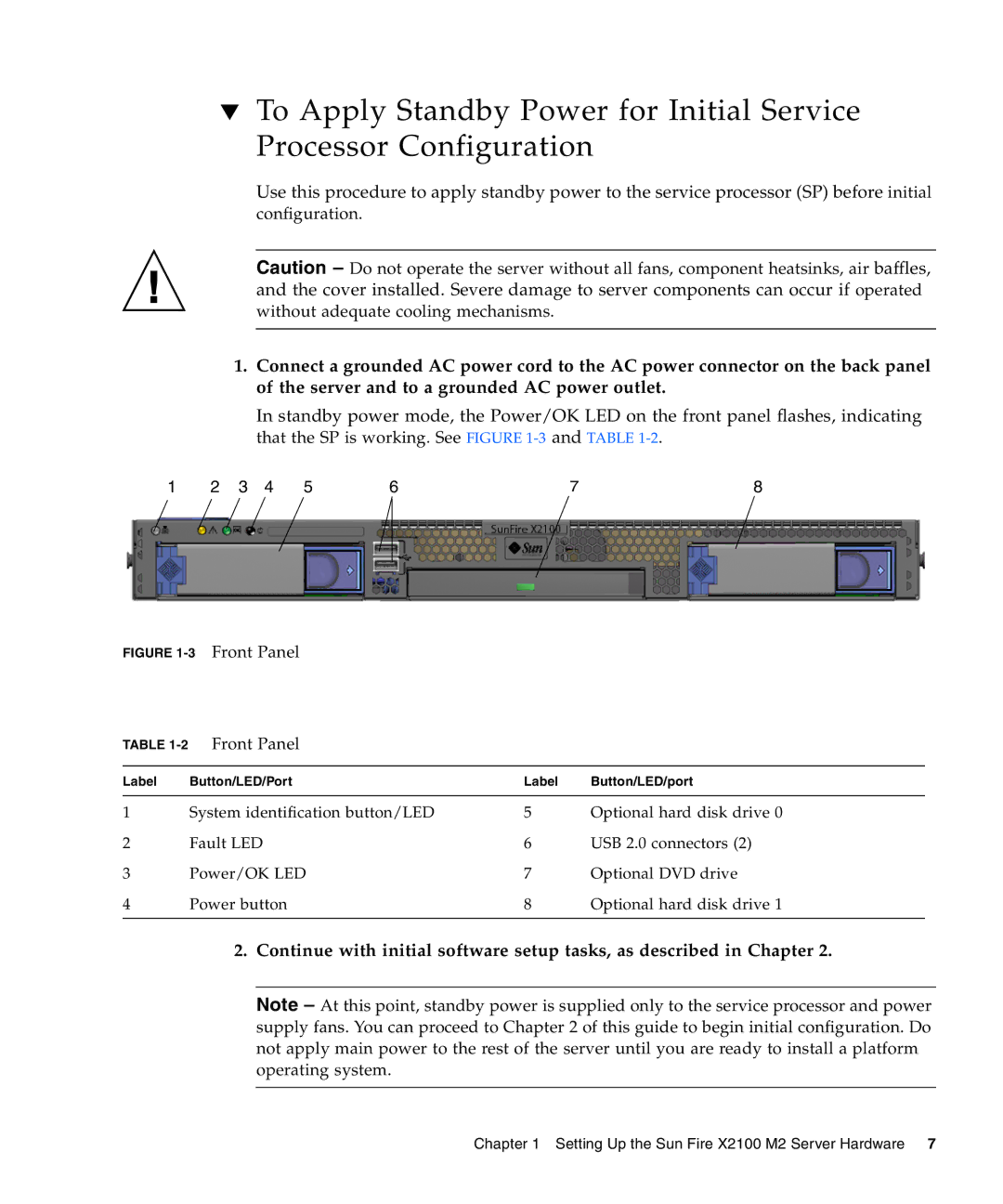
In standby power mode, the Power/OK LED on the front panel flashes, indicating that the SP is working. See FIGURE
1 | 2 | 3 | 4 | 5 | 6 | 7 | 8 |
FIGURE 1-3 Front Panel
TABLE | Front Panel |
|
|
|
|
|
|
Label | Button/LED/Port | Label | Button/LED/port |
|
|
|
|
1 | System identification button/LED | 5 | Optional hard disk drive 0 |
2 | Fault LED | 6 | USB 2.0 connectors (2) |
3 | Power/OK LED | 7 | Optional DVD drive |
4 | Power button | 8 | Optional hard disk drive 1 |
|
|
|
|
2.Continue with initial software setup tasks, as described in Chapter 2.
Note – At this point, standby power is supplied only to the service processor and power supply fans. You can proceed to Chapter 2 of this guide to begin initial configuration. Do not apply main power to the rest of the server until you are ready to install a platform operating system.
Chapter 1 Setting Up the Sun Fire X2100 M2 Server Hardware 7