SUPERSERVER
Ethernet Ports
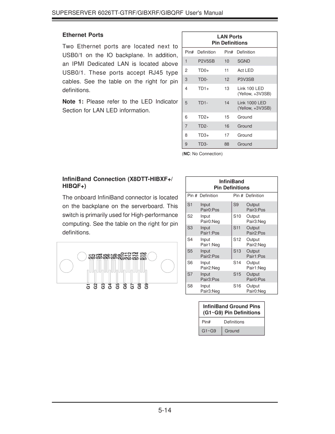
Two Ethernet ports are located next to USB0/1 on the IO backplane. In addition, an IPMI Dedicated LAN is located above USB0/1. These ports accept RJ45 type cables. See the table on the right for pin definitions.
Note 1: Please refer to the LED Indicator Section for LAN LED information.
LAN Ports
Pin Definitions
Pin# | Definition | Pin# | Definition |
1 | P2V5SB | 10 | SGND |
2 | TD0+ | 11 | Act LED |
3 | TD0- | 12 | P3V3SB |
4 | TD1+ | 13 | Link 100 LED |
|
|
| (Yellow, +3V3SB) |
5 | TD1- | 14 | Link 1000 LED |
|
|
| (Yellow, +3V3SB) |
6 | TD2+ | 15 | Ground |
7 | TD2- | 16 | Ground |
8 | TD3+ | 17 | Ground |
9 | TD3- | 88 | Ground |
(NC: No Connection)
InfiniBand Connection (X8DTT-HIBXF+/ HIBQF+)
InfiniBand
Pin Definitions
The onboard InfiniBand connector is located on the backplane on the serverboard. This switch is primarily used for
S2 S3 | S5 | S7 | S10 S11 S12 S13 S14 | S15 S16 | |
S1 | S4 | S6 | S8 S9 |
| |
G1 | G2 | G3 | G4 | G5 | G6 | G7 | G8 | G9 |
Pin # Definition
S1 Input
Pair0:Pos
S2 Input
Pair0:Neg
S3 Input
Pair1:Pos
S4 Input Pair1:Neg
S5 Input
Pair2:Pos
S6 Input
Pair2:Neg
S7 Input
Pair3:Pos
S8 Input
Pair3:Neg
Pin # Definition
S9 Output
Pair3:Pos
S10 Output
Pair3:Neg
S11 Output
Pair2:Pos
S12 Output
Pair2:Neg
S13 Output
Pair1:Pos
S14 Output
Pair1:Neg
S15 Output
Pair0:Pos
S16 Output
Pair0:Neg
InfiniBand Ground Pins (G1~G9) Pin Definitions
Pin# Definitions
G1~G9 | Ground |
|
|
