![]()
![]()
![]()
![]()
![]()
![]()
2-6 Control Panel Connectors and I/O Ports
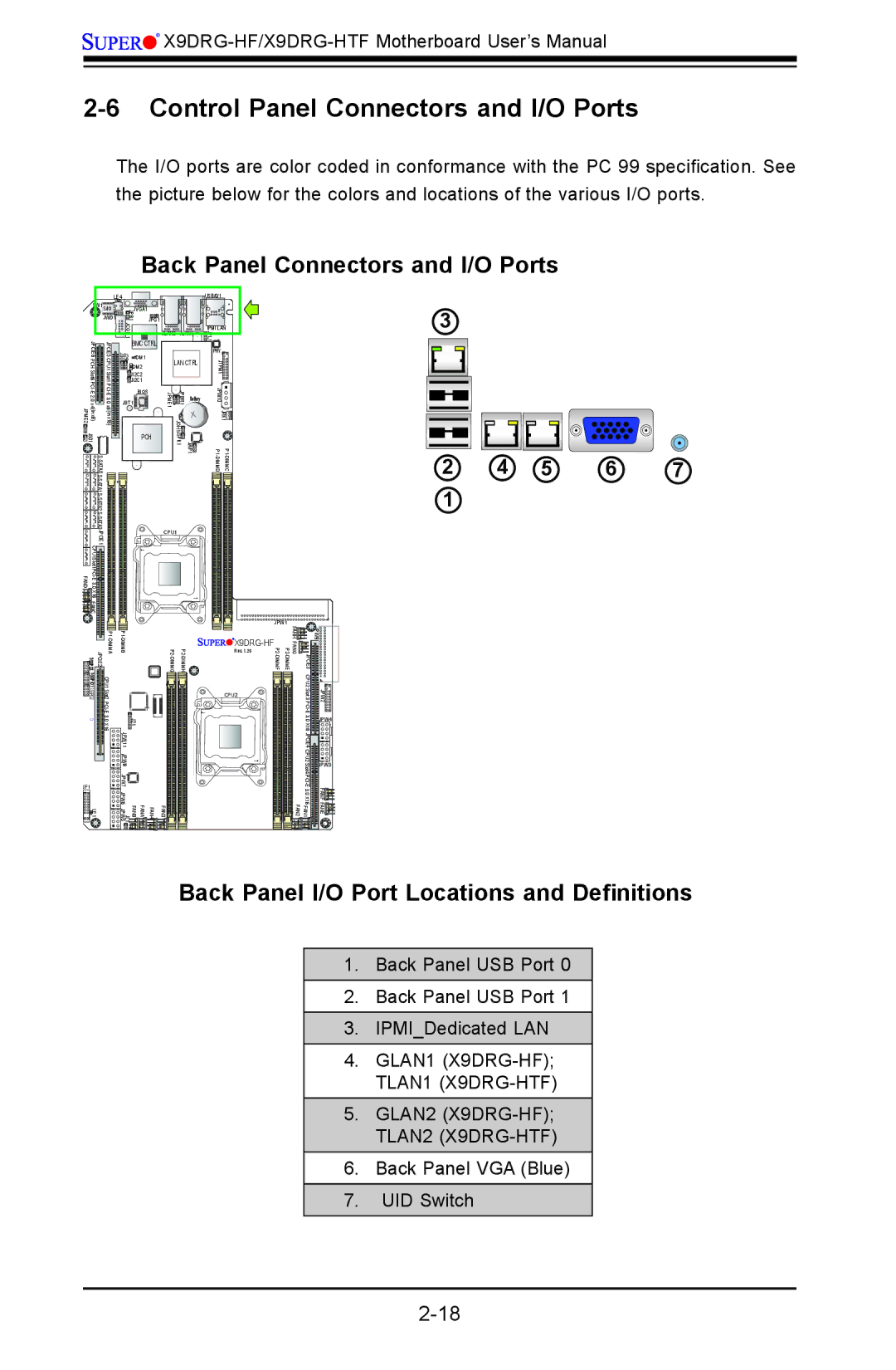
The I/O ports are color coded in conformance with the PC 99 specification. See the picture below for the colors and locations of the various I/O ports.
Back Panel Connectors and I/O Ports
|
| LE4 |
| |
| SW1 S/IO | JVGA1 | ||
|
| JWD1 | JPB1 | JPG1 |
|
|
| JCOM1 |
|
| JPCIE6 | JPCIE5 | BMC CTRL | |
| J29 J30 | DM1 | ||
DM2 | ||||
|
|
| JI2C2 | |
|
|
| JI2C1 | |
|
|
|
| BIOS |
|
|
| JBT1 |
|
JSD1 |
|
| PCH | |
A0AT |
| A0AT |
|
|
|
|
| ||
|
|
| ||
|
|
|
| |
|
|
| ||
| JPCIE1 |
|
| |
FAND |
|
| ||
|
|
|
| |
| X16 |
|
| |
| FANC |
|
|
|
|
|
| USB/0/1 | |
JLAN2 | JLAN1 | IPMI LAN | ||
JPL1 | ||||
|
|
| ||
|
|
| PHY | |
LAN CTRL | JTPM1 | |||
|
|
| ||
JPME1 | JPBR1 | Battery | JPW10 | |
| JOH1 |
| JRK1 | |
| JWP1 JSPK1 | |||
CPU1
3
2 | 4 | 5 | 6 | 7 |
1 |
|
|
|
|
JPCIE2 ![]() T-SGPIO5
T-SGPIO5![]()
CPU1 Slot2 | J21 1 |
| JPW 1 |
| JPW1 |
|
|
| Rev. 1.20 |
CPU2 |
FANH | JPW9 |
FANG |
|
JPCIE3 |
|
CPU2 Slot 3PCI | JPW2 |
JPW4 | |
X16 JPCIE4 |
|
JF1 ![]()
![]()
![]() LE1
LE1
JPW8 |
JPW7 |
JPW6 |
FANA FANB JL1 JPW5 |
| CPU2 | JPW3 |
| Slot4 | |
| FANF | |
FAN3 FAN4 | FAN1 FAN2 | FANE |
Back Panel I/O Port Locations and Definitions
1.Back Panel USB Port 0
2.Back Panel USB Port 1
3.IPMI_Dedicated LAN
4.GLAN1
5.GLAN2
6.Back Panel VGA (Blue)
7.UID Switch