|
| Table of Contents |
|
|
|
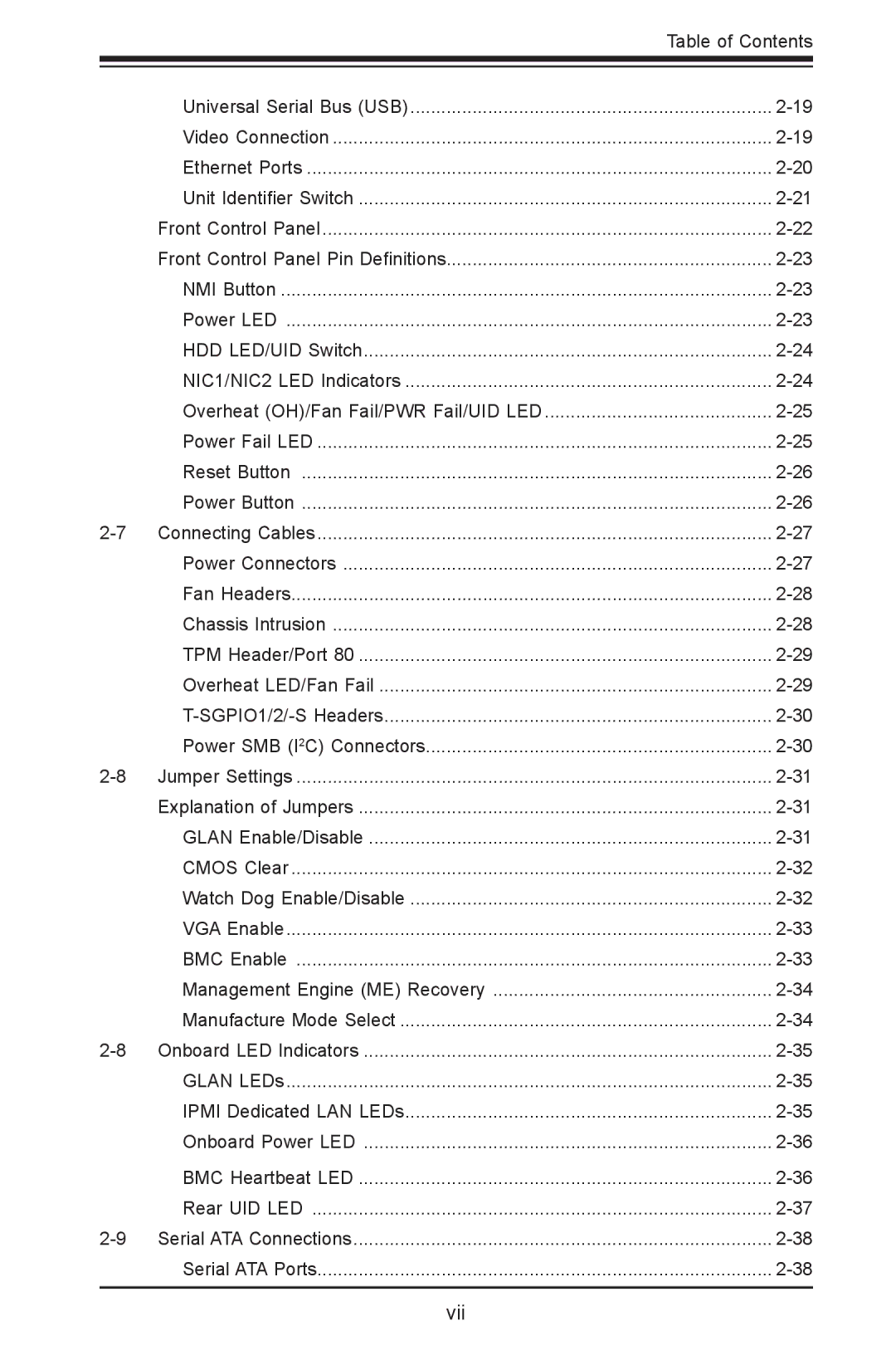
| Universal Serial Bus (USB) | |
| Video Connection | |
| Ethernet Ports | |
| Unit Identifier Switch | |
| Front Control Panel | |
| Front Control Panel Pin Definitions | |
| NMI Button | |
| Power LED | |
| HDD LED/UID Switch | |
| NIC1/NIC2 LED Indicators | |
| Overheat (OH)/Fan Fail/PWR Fail/UID LED | |
| Power Fail LED | |
| Reset Button | |
| Power Button | |
Connecting Cables | ||
| Power Connectors | |
| Fan Headers | |
| Chassis Intrusion | |
| TPM Header/Port 80 | |
| Overheat LED/Fan Fail | |
| ||
| Power SMB (I2C) Connectors | |
Jumper Settings | ||
| Explanation of Jumpers | |
| GLAN Enable/Disable | |
| CMOS Clear | |
| Watch Dog Enable/Disable | |
| VGA Enable | |
| BMC Enable | |
| Management Engine (ME) Recovery | |
| Manufacture Mode Select | |
Onboard LED Indicators | ||
| GLAN LEDs | |
| IPMI Dedicated LAN LEDs | |
| Onboard Power LED | |
| BMC Heartbeat LED | |
| Rear UID LED | |
Serial ATA Connections | ||
| Serial ATA Ports | |
|
|
|
Page 7
Image 7
