Chapter 2: Installation
Unit Identifier Switch
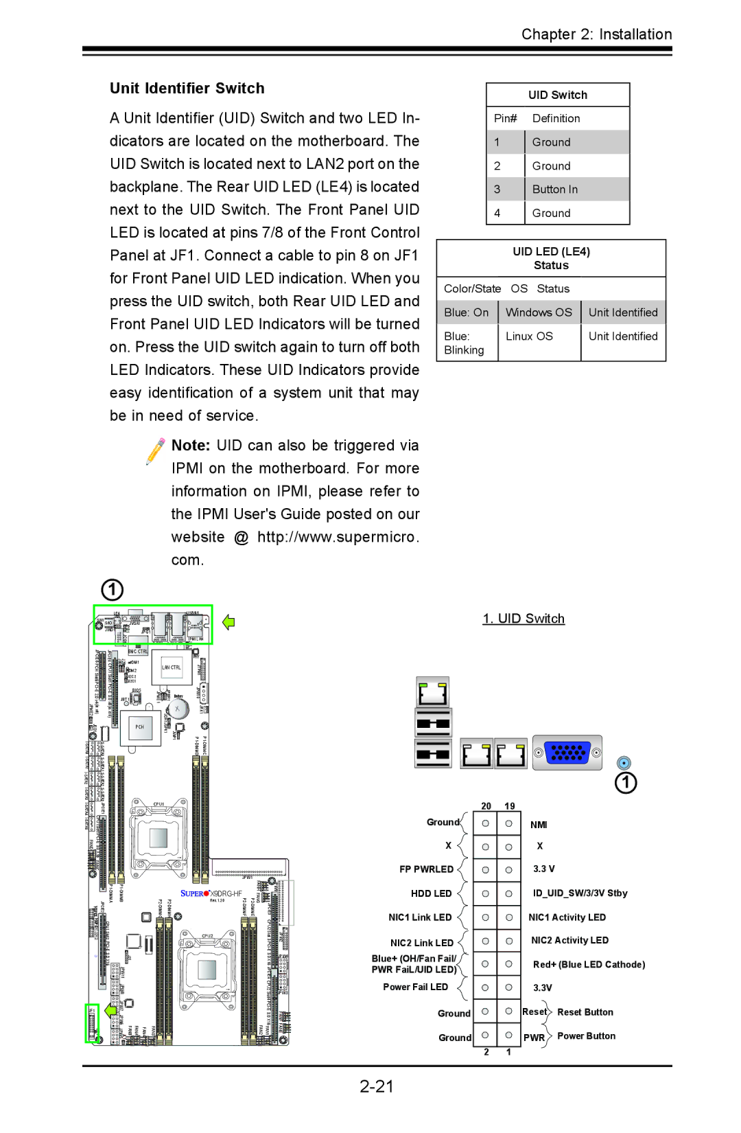
A Unit Identifier (UID) Switch and two LED In- dicators are located on the motherboard. The UID Switch is located next to LAN2 port on the backplane. The Rear UID LED (LE4) is located next to the UID Switch. The Front Panel UID LED is located at pins 7/8 of the Front Control Panel at JF1. Connect a cable to pin 8 on JF1 for Front Panel UID LED indication. When you press the UID switch, both Rear UID LED and Front Panel UID LED Indicators will be turned on. Press the UID switch again to turn off both LED Indicators. These UID Indicators provide easy identification of a system unit that may be in need of service.
Note: UID can also be triggered via IPMI on the motherboard. For more information on IPMI, please refer to the IPMI User's Guide posted on our website @ http://www.supermicro. com.
1
UID Switch
Pin# Definition
1Ground
2Ground
3Button In
4Ground
UID LED (LE4)
Status
Color/State | OS Status |
| |
|
|
| |
Blue: On |
| Windows OS | Unit Identified |
|
|
|
|
Blue: |
| Linux OS | Unit Identified |
Blinking |
|
|
|
|
|
|
|
| LE4 |
| |
SW1 S/IO | JVGA1 | ||
| JWD1 | JPB1 | JPG1 |
|
| JCOM1 |
|
JPCIE6 | JPCIE5 | BMC CTRL | |
J29 J30 | DM1 | ||
PCH Slot6 | CPU1 Slot1 | DM2 | |
JI2C2 | |||
JI2C1 | |||
| BIOS | ||
JBT1 |
| ||
|
| ||
JSD1 | A0AT |
| PCH |
A0AT |
|
| |
|
| ||
S- |
|
| |
A2AT | SA2AT |
|
|
|
| ||
|
| ||
A4 |
|
|
|
|
|
| USB/0/1 | |
JLAN2 | JLAN1 | IPMI LAN | ||
JPL1 | ||||
|
|
| ||
|
|
| PHY | |
LAN CTRL | JTPM1 | |||
|
|
| ||
JPME1 | JPBR1 | Battery | JPW10 | |
| JOH1 |
| JRK1 | |
| JWP1 JSPK1 | |||
1. UID Switch
1
JPCIE1 |
| |
|
| |
| ||
X16 |
| |
FANC |
|
|
CPU1 Slot2 |
| |
| J21 1 | |
|
| JPW 1 |
|
| JPW8 |
JF1 |
| JPW7 |
| JPW6 | |
|
| |
LE1 | FAN4 FANA FANB JL1 JPW5 | |
CPU1
|
| JPW1 |
|
| |
|
|
| FANH |
| JPW9 |
|
| FANG |
|
| |
|
| Rev. 1.20 |
|
| |
JPCIE3 |
| ||||
|
|
|
| CPU2 |
|
|
| CPU2 |
| Slot 3 PCI | JPW2 |
|
|
|
| ||
|
|
|
| JPW4 | |
|
|
|
| X16 JPCIE4 CPU2 | JPW3 |
|
|
|
| Slot4 | |
|
|
|
| FANF | |
FAN3 |
|
| FAN1 FAN2 | FANE | |
Ground![]()
X
FP PWRLED ![]()
HDD LED
NIC1 Link LED ![]()
NIC2 Link LED
Blue+ (OH/Fan Fail/
PWR FaiL/UID LED)
Power Fail LED
Ground
Ground
20 | 19 |
2 1
NMI
X
3.3 V
ID_UID_SW/3/3V Stby
NIC1 Activity LED
NIC2 Activity LED
Red+ (Blue LED Cathode)
3.3V
Reset Reset Button
PWR Power Button