Chapter 2: Installation
Universal Serial Bus (USB)
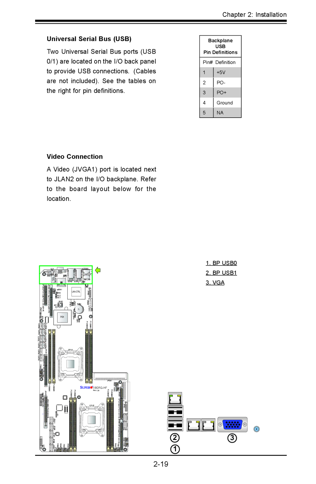
Two Universal Serial Bus ports (USB 0/1) are located on the I/O back panel to provide USB connections. (Cables are not included). See the tables on the right for pin definitions.
Video Connection
Backplane
USB
Pin Definitions
Pin# Definition
1+5V
2PO-
3PO+
4Ground
5NA
A Video (JVGA1) port is located next to JLAN2 on the I/O backplane. Refer to the board layout below for the location.
|
| LE4 |
| |
| SW1 S/IO | JVGA1 | ||
|
| JWD1 | JPB1 | JPG1 |
|
|
| JCOM1 |
|
| JPCIE6 | JPCIE5 | BMC CTRL | |
| J29 J30 | DM1 | ||
DM2 | ||||
|
|
| JI2C2 | |
|
|
| JI2C1 | |
|
|
|
| BIOS |
|
|
| JBT1 |
|
JSD1 | A0AT |
| PCH | |
A0AT |
|
|
| |
|
|
| ||
| S- |
|
| |
A2AT |
| SA2AT |
|
|
|
|
| ||
|
|
| ||
| JPCIE1 |
|
| |
FAND |
|
| ||
|
|
|
| |
| X16 |
|
| |
| FANC |
|
|
|
|
|
| USB/0/1 | |
JLAN2 | JLAN1 | IPMI LAN | ||
JPL1 | ||||
|
|
| ||
|
|
| PHY | |
LAN CTRL | JTPM1 | |||
|
|
| ||
JPME1 | JPBR1 | Battery | JPW10 | |
| JOH1 |
| JRK1 | |
| JWP1 JSPK1 | |||
CPU1
1.BP USB0
2.BP USB1
3.VGA
JPCIE2 ![]() T-SGPIO5
T-SGPIO5![]()
![]()
![]()
![]()
![]()
JF1
![]()
![]()
![]() LE1
LE1
CPU1 Slot2 | J21 1 |
| JPW 1 |
| JPW8 |
| JPW7 |
| JPW6 |
| FANA FANB JL1 JPW5 |
|
| JPW1 |
|
| |
|
|
| FANH |
| JPW9 |
|
| FANG |
|
| |
|
| Rev. 1.20 |
|
| |
JPCIE3 |
| ||||
|
|
|
| CPU2 |
|
|
| CPU2 |
| Slot 3 PCI | JPW2 |
|
|
|
| ||
|
|
|
| JPW4 | |
|
|
|
| X16 JPCIE4 |
|
|
| CPU2 | JPW3 |
|
|
|
| Slot4 |
|
| |
|
| FANF | 2 | 3 | |
FAN4 | FAN3 | FAN1 FAN2 | FANE | 1 |
|
|
|
|
|
|