Chapter 2: Installation
Overheat (OH)/Fan Fail/PWR Fail/UID
LED
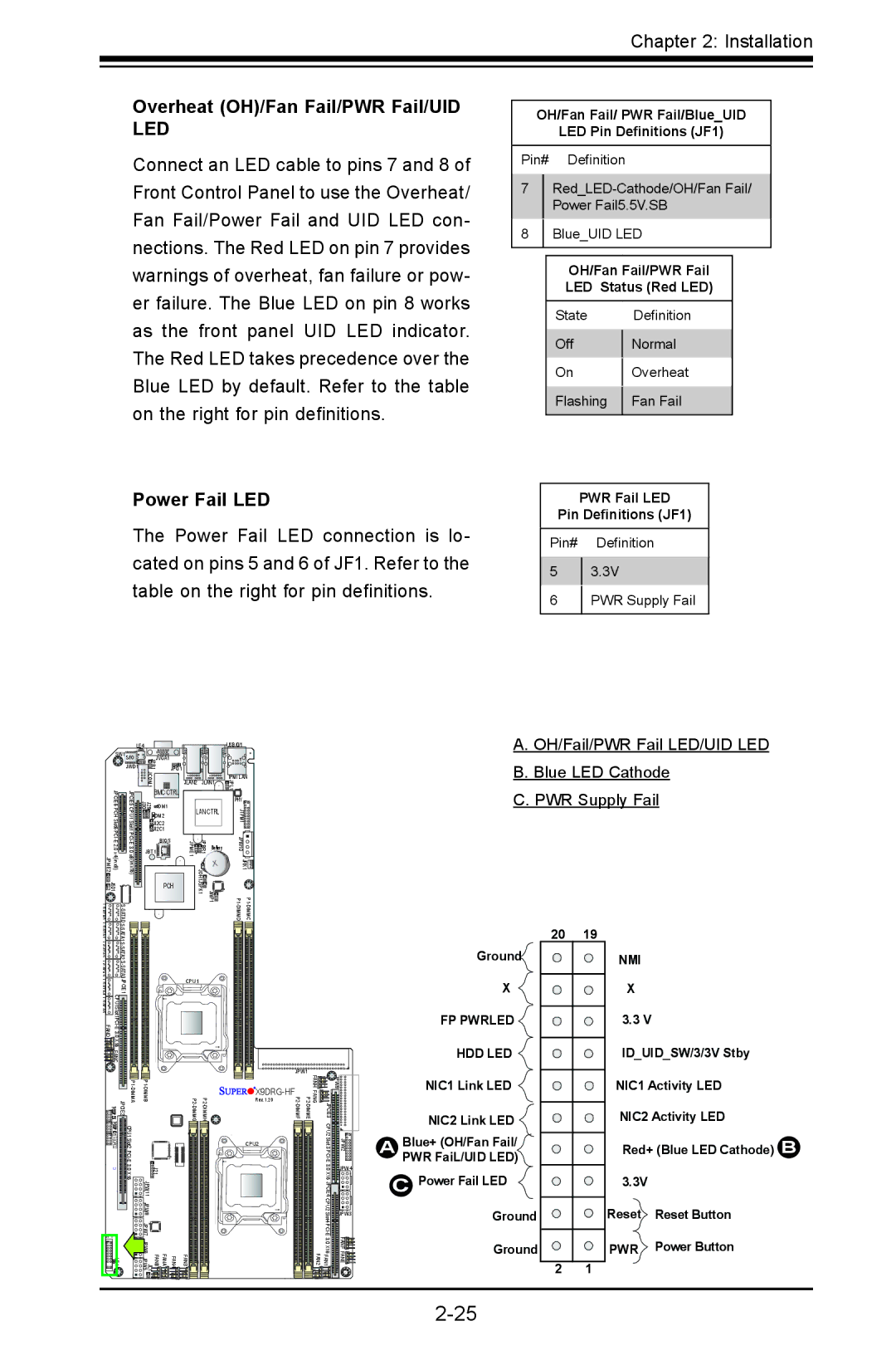
Connect an LED cable to pins 7 and 8 of Front Control Panel to use the Overheat/ Fan Fail/Power Fail and UID LED con- nections. The Red LED on pin 7 provides warnings of overheat, fan failure or pow- er failure. The Blue LED on pin 8 works as the front panel UID LED indicator. The Red LED takes precedence over the Blue LED by default. Refer to the table on the right for pin definitions.
Power Fail LED
The Power Fail LED connection is lo- cated on pins 5 and 6 of JF1. Refer to the table on the right for pin definitions.
OH/Fan Fail/ PWR Fail/Blue_UID
LED Pin Definitions (JF1)
Pin# Definition
7
Power Fail5.5V.SB
8Blue_UID LED
OH/Fan Fail/PWR Fail
LED Status (Red LED)
State |
| Definition |
Off |
| Normal |
| ||
On |
| Overheat |
| ||
Flashing |
| Fan Fail |
| ||
|
|
|
PWR Fail LED
Pin Definitions (JF1)
Pin# Definition
53.3V
6PWR Supply Fail
|
| LE4 |
|
|
|
| USB/0/1 |
| |
| SW1 S/IO | JVGA1 |
|
|
|
|
| ||
|
| JWD1 | JPB1 | JPG1 |
|
|
|
|
|
|
|
| JCOM1 |
| JLAN2 | JLAN1 | IPMI LAN | ||
|
|
|
| JPL1 |
| ||||
|
|
|
|
|
|
|
| ||
| JPCIE6 | JPCIE5 | BMC CTRL |
|
|
| PHY |
| |
| J30 | DM1 |
|
|
|
| |||
| LAN CTRL | JTPM1 |
| ||||||
| DM2 |
| |||||||
| J29 |
|
|
|
|
| |||
JI2C2 |
|
|
|
|
| ||||
JI2C1 |
|
|
|
|
| ||||
| BIOS | JPME1 | JPBR1 | Battery | JPW10 |
| |||
JBT1 |
|
| |||||||
| PCH | JOH1 |
| JRK1 | |||||
| JSD1 |
|
|
| JSPK1 | JWP1 |
|
| |
A0AT |
|
|
| ||||||
I- |
| S |
|
|
|
|
|
|
|
A. OH/Fail/PWR Fail LED/UID LED
B. Blue LED Cathode
C. PWR Supply Fail
S A2AT |
|
|
|
|
| |
|
|
|
|
| ||
|
|
|
|
| ||
JPCIE1 |
| CPU1 |
|
|
| |
|
|
|
|
| ||
|
|
|
|
|
| |
|
|
|
|
| ||
X16 |
|
|
|
|
| |
FANC |
|
|
|
|
|
|
|
|
|
| JPW1 |
|
|
|
|
|
|
|
|
|
|
|
|
| Rev. 1.20 |
|
|
| FANHFANG | JPCIE3 | JPW9 | |||
SGPIO1 | CPU1 Slot2 |
|
| CPU2 | CPU2 Slot 3 | JPW2 |
|
|
| ||||
| 3.0 X16 | J21 1 |
|
| 3.0 X16 | JPW4 |
|
|
|
| |||
|
| JPW 1 |
|
| JPCIE4 |
|
|
| JPW8 |
|
| CPU2 Slot4 | JPW3 |
|
|
|
|
| ||
JF1 |
| JPW7 |
|
|
| FANF FANE |
|
|
|
| 3 | ||
|
| FAN4 FANA FANB JPW6 JL1 JPW5 |
|
| .0 X16 | |
LE1 | FAN3 | FAN1 FAN2 | ||||
Ground![]()
X
FP PWRLED ![]()
HDD LED
NIC1 Link LED ![]()
NIC2 Link LED
ABlue+ (OH/Fan Fail/ PWR FaiL/UID LED)
CPower Fail LED ![]() Ground
Ground
Ground
20 19
2 1
NMI
X
3.3 V
ID_UID_SW/3/3V Stby
NIC1 Activity LED
NIC2 Activity LED
Red+ (Blue LED Cathode) B
3.3V
Reset Reset Button
PWR Power Button